Large-deformation tunnel body supporting structure of soft rock tunnel in wrinkled area and construction method of large-deformation tunnel body supporting structure

A support structure and large deformation technology, applied in tunnels, tunnel linings, earthwork drilling and mining, etc., can solve problems such as low yield, easy loose vaults, and collapse, and achieve high practicability, economical convenience, and strong pertinence Effect

Pending Publication Date: 2022-08-02
CCCC SECOND HARBOR ENG
View PDF0 Cites 0 Cited by
  • Summary
  • Abstract
  • Description
  • Claims
  • Application Information

AI Technical Summary

Problems solved by technology

[0003] The main purpose of the present invention is to provide a large-deformation cave body support structure and construction method of a soft rock tunnel in a fold area, which solves the problem that the weak surrounding rock is easily loosened and the vault collapses after being affected by the stress concentration, while the traditional support The hanging net spraying in the method has little effect on solving such problems; at the same time, because the surrounding rock at the front end of the face is affected by the stress concentration, the cracks in the surrounding rock are tightly closed, which limits the advance grouting, resulting in loose surrounding rock gravel after excavation. After thawing, pouring along the gap of the initial support arch continued to cause the problem that the deformation of the cave body did not converge

Method used


Image

  • Large-deformation tunnel body supporting structure of soft rock tunnel in wrinkled area and construction method of large-deformation tunnel body supporting structure
  • Large-deformation tunnel body supporting structure of soft rock tunnel in wrinkled area and construction method of large-deformation tunnel body supporting structure
  • Large-deformation tunnel body supporting structure of soft rock tunnel in wrinkled area and construction method of large-deformation tunnel body supporting structure

Examples


Embodiment 1

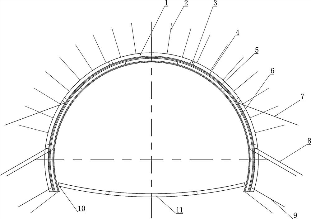
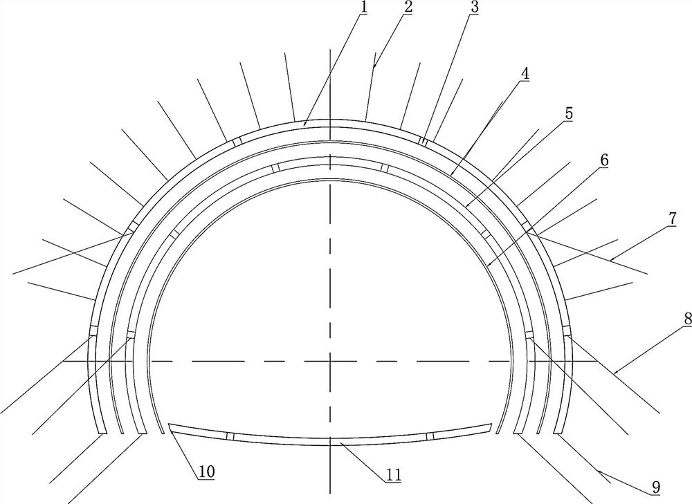
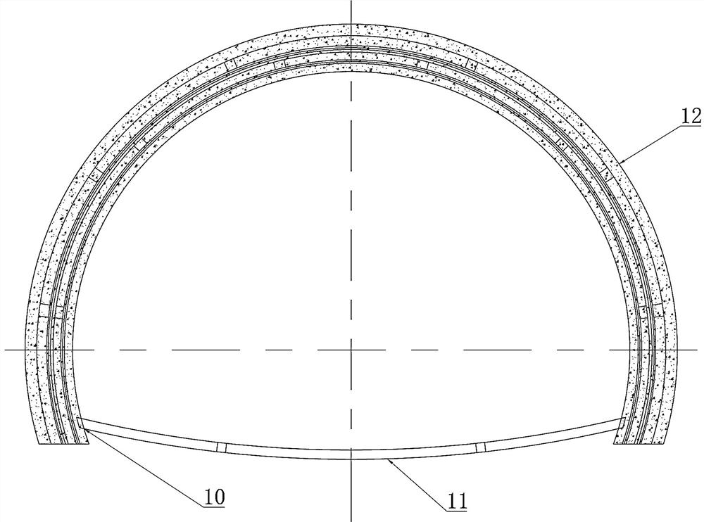
[0049] like Figure 1~17As shown in the figure, a large deformation tunnel body supporting structure of a soft rock tunnel in a folded area consists of a plurality of steel bodies to form a grid arch frame 1 of a ring structure, and a plurality of steel bodies are arranged inside the grid arch frame 1 to form a ring structure steel arch frame 5, between the steel arch 5 and the grille arch 1, an outer layer of steel mesh 4 is provided, the inner wall of the steel arch 5 is provided with an inner layer of steel mesh 6, and the bottom opening of the steel arch 5 is provided with a lower step arch 11, The lower step arch 11 and the steel arch 5 form a closed loop. The outer wall of the grille arch 1 is also provided with a plurality of vertically arranged steel flower tubes 2 . The outside of the steel arch 5 and the grid arch 1 are also provided with a plurality of locking foot anchor pipes inclined downward. The grid arch 1 , the lower step arch 11 and the steel arch 5 are al...

Embodiment 2

[0053] like Figures 8~13 As shown, in the preferred solution, the structure of the first arch connector 3 is as follows: the two sides of the second fixing plate 104 of the second steel body 102 are provided with positioning claws 301, and the positioning claws 301 pass through the second fixing plate 104 and The rotating shaft 302 is connected, the two sides of the first fixing plate 103 of the first steel body 101 are clamped on the positioning claws 301, and the first fixing plate 103 and the second fixing plate 104 are connected by a plurality of double-headed nuts. The grid arch 1 , the lower step arch 11 and the steel arch 5 are all assembled by connecting rigid bodies through the first arch connecting head 3 . The first arch connecting head 3 is mainly connected by a plurality of double-headed nuts through the first fixing plate 103 and the second fixing plate 104, and is simply positioned by the positioning claws 301, and then the grille arch 1, the lower step arch 11...

Embodiment 3

[0060] like Figures 14~17 As shown, in the preferred solution, the lower step arch 11 and the steel arch 5 are connected by a second arch connecting head 10 . The structure of the second arch frame connector 10 is as follows: a third fixing plate 501 is provided on one side of the steel arch 5 , limiting claws 1001 are arranged on both sides of the third fixing plate 501 , and the limiting claws 1001 pass through the third fixing plate 501, and a limit plate 1002 is provided at the end of the limit claw 1001, the fourth fixed plate 1101 at the end of the lower step arch 11 is clamped on the limit claw 1001, and the fourth fixed plate 1101 and the third fixed plate 501 pass through A plurality of studs are connected; the second arch connector 10 can connect the steel arch 5 and the lower step arch 11, and the angle between the lower step arch 11 and the steel arch 5 can pass through the second arch connector 10 to adjust, the limiting claw 1001 is used to limit the position o...


PUM


Abstract

The invention provides a large-deformation tunnel body supporting structure of a soft rock tunnel in a wrinkled area and a construction method. A plurality of steel bodies form a grating arch frame of an annular structure, a plurality of steel bodies are arranged on the inner side of the grating arch frame to form a steel arch frame of the annular structure, an outer-layer reinforcing mesh is arranged between the steel arch frame and the grating arch frame, and an inner-layer reinforcing mesh is arranged on the inner wall of the steel arch frame; a lower step arch frame is arranged at the opening position of the bottom of the steel arch frame, and the lower step arch frame and the steel arch frame form a closed loop. A supporting structure of sprayed concrete, a double-layer arch frame, a reinforcing mesh, radial grouting and a steel pipe large locking foot is designed, after an excavation face is initially stabilized through primary spraying of the sprayed concrete, the double-layer arch frame is installed to form a yielding supporting structure, meanwhile, surrounding rock of a loose circle of a tunnel body is solidified through radial grouting, and finally a supporting system is formed by hanging the mesh and re-spraying the concrete to the designed thickness.

Description

technical field [0001] The invention relates to the field of steel arch frame construction, in particular to a large deformation tunnel body support structure and a construction method for a soft rock tunnel in a folded area. Background technique [0002] With the rapid development of highway engineering in my country, the geological background faced by the engineering construction has become more and more complex, and the tunnel, as a construction project excavating through geological rock layers, is more affected by geological factors such as stratum and structure. In recent years, the large deformation problem of soft rock tunnels passing through folded areas has always been a hotspot in the field of tunnel construction. Through the study of tectonic stress and surrounding rock lithology in folded areas, the combination of release and resistance based on unloading and high in-situ stress has been developed in engineering. According to the supporting principle, the support...

Claims


Application Information

Patent Timeline
Patent Type & Authority Applications(China)
IPC IPC(8): E21D11/18E21D11/15E21D20/00E21D11/10
CPCE21D11/18E21D11/152E21D20/00E21D11/10
Inventor 王添新张亚平吴银宝易帅徐庭陈为民万猛薛克进陈丹孙小强张晓光李小童刘东兴刘康冉路尧李鸿飞
Owner CCCC SECOND HARBOR ENG
Why Eureka
Try Eureka