Preparation device of vapor chamber wick and preparation method of wick

A technology for preparing a device and a liquid absorbing core, which is applied in the field of preparing devices for a liquid soaking core of a vapor chamber, can solve the problems of increased material cost, low thermal resistance coefficient heat dissipation power, complicated process, etc., and achieves low equipment and processing costs, low thermal resistance. coefficient, the effect of high heat dissipation power

Pending Publication Date: 2022-08-05
中山市仲德科技有限公司
View PDF0 Cites 0 Cited by
  • Summary
  • Abstract
  • Description
  • Claims
  • Application Information

AI Technical Summary

Problems solved by technology

[0003] The current vapor chamber manufacturing method still has defects: 1. Groove: multiple grooves in the same direction are formed on the inner surface
After high-temperature heat treatment, the strength of the base material is reduced, and it is not easy to be thinned, which increases the cost of materials
[0006] 4. Foamed metal: The foamed metal is a capillary structure, and the foamed metal is not easy to control the size of the pores, and the process is unstable.
[0007] 5. Fix the pre-laid capillary structure with copper springs: the process is complicated and the combination is poor, resulting in poor heat dissipation effect
The heat dissipation effect is good, but the process is complicated, the equipment is expensive, and the process must be heated to a high temperature to soften the substrate
[0009] 7. Use photolithography or precision electroforming to manufacture metal microstructures: This method can produce uniform and fine capillary structures, but its manufacturing cost is expensive
[0010] 8. Using the active ion etching method of the semiconductor process to etch the capillary structure on the silicon substrate: the capillary structure formed by this method has strong capillary force, but the materials used are limited by the semiconductor process, and the manufacturing cost is expensive
[0011] 9. Form a capillary structure with high porosity on the vapor chamber by electrochemical method: it can achieve thin structure, low thermal resistance coefficient, high heat dissipation power, simplified process, stable quality, low equipment and processing costs, and reduce manufacturing costs. However, due to the thinning of the vapor chamber, it is easy to deform the thin plate due to liquid resistance when it is placed in the electrolyte, which affects the final effect of the product.

Method used


Image

  • Preparation device of vapor chamber wick and preparation method of wick
  • Preparation device of vapor chamber wick and preparation method of wick

Examples


Embodiment Construction

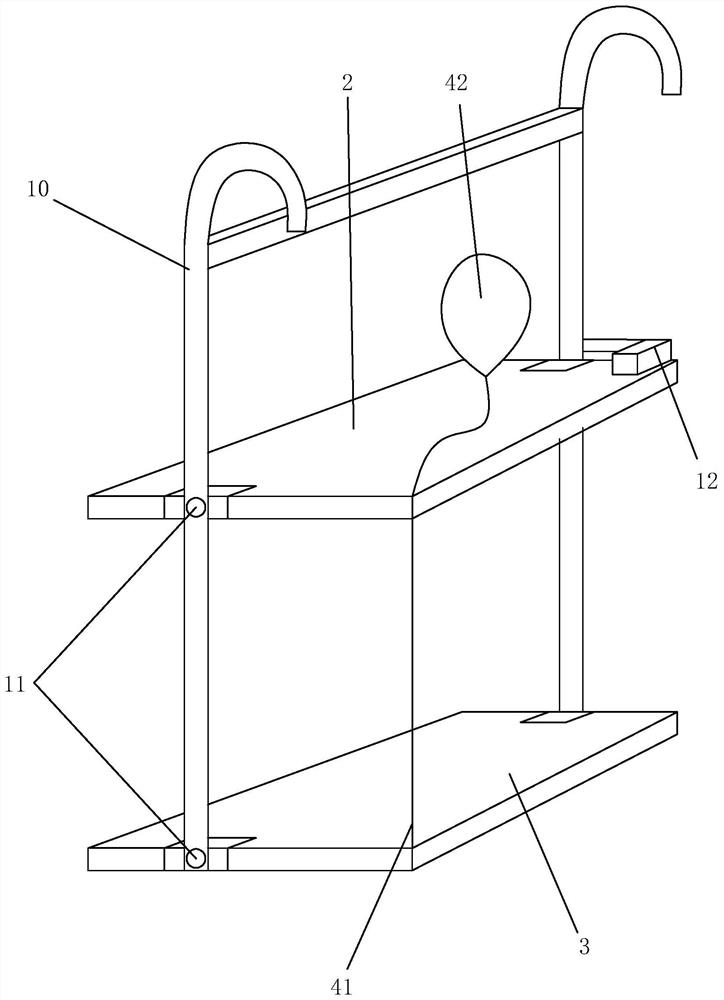
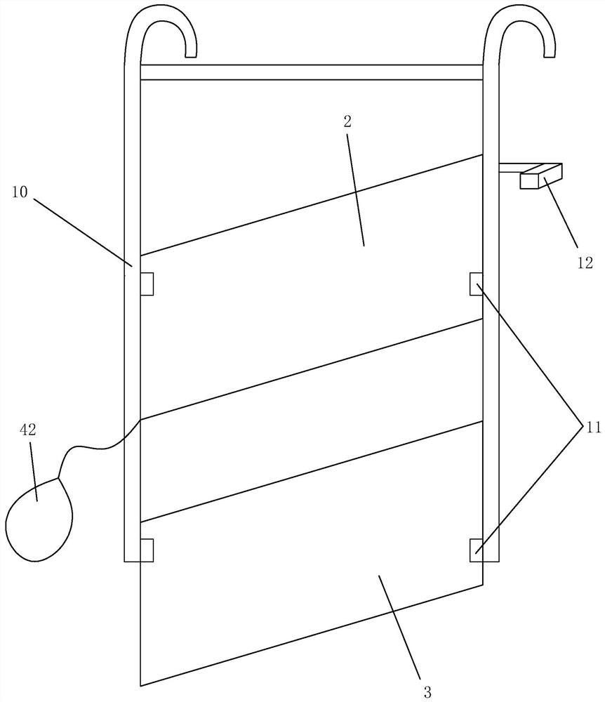
[0035] like figure 1 As shown, the present application is a preparation device for a soaking plate liquid absorbent core, including an electroplating hanger 1 , an upper plate 2 , a lower plate 3 , a rotating mechanism 11 and a buoyancy mechanism 4 .

[0036] The present application provides an apparatus for preparing a liquid absorbent core for a vapor chamber, including an electroplating hanger, wherein the electroplating hanger includes two fixed rods 10 that are vertically arranged opposite each other, and are hinged to one of the two fixed rods 10 through a rotating mechanism 11 . The upper plate 2 and the lower plate 3 between the upper plate 2 and the lower plate 3, the rotating mechanism 11 is arranged at the offset of the center of gravity of the upper plate 2 and the lower plate 3, so that the upper plate 2 and the lower plate 3 are not placed When entering the electrolyte, it is in a vertical state, and a buoyancy mechanism 4 is provided at the offset of the other s...


PUM


Abstract

The invention provides a preparation device of a vapor chamber wick, which has the advantages of thin structure, low thermal resistance coefficient, high heat dissipation power, simplified process, stable quality, low equipment and processing cost, reduced reject ratio of manufacture and the like, and is not easy to be damaged due to the overlarge thin plate during electroplating. And upward bending deformation is caused by liquid resistance when the battery is placed in electrolyte.

Description

technical field [0001] The application relates to the technical field of vapor chamber production, and in particular to a device for preparing a liquid absorbent core for a vapor chamber and a method for preparing a liquid absorbent core. Background technique [0002] With the progress and development of science and technology, the demand for heat dissipation of today's electronic equipment is also getting higher and higher. The principle of widely used heat dissipation technology is to combine a capillary structure layer on the inner wall of the closed cavity, and inject the working fluid after vacuuming. , and the space in the middle is used for steam flow; the operation is to use the saturated steam pressure difference between the cold and hot ends to make the steam at the hot end flow to the cold end, so that the liquid at the hot end continues to evaporate and absorb heat, and the condensing end releases heat and condenses to achieve for fast heat transfer. The above-m...

Claims


Application Information

Patent Timeline
Patent Type & Authority Applications(China)
IPC IPC(8): C25D17/08C25D17/00F28D15/04C25D5/02
CPCC25D17/08C25D17/00C25D5/022F28D15/046Y02P10/20
Inventor 邵志松周韦郭大祺
Owner 中山市仲德科技有限公司
Why Eureka
Try Eureka