Supercharge Your Innovation With Domain-Expert AI Agents!

Wire cut electrical discharge machining device and method capable of conducting rough machining and finish machining synchronously

A technology of electric discharge wire and cutting device, which is applied in the direction of accessory devices, metal processing equipment, electric processing equipment, etc., can solve the problems of large processing error, low processing efficiency, and limitation of processing efficiency, so as to reduce processing current and improve The effect of improving processing efficiency and processing accuracy

Pending Publication Date: 2022-08-09
GUANGDONG UNIV OF TECH
View PDF6 Cites 0 Cited by
  • Summary
  • Abstract
  • Description
  • Claims
  • Application Information

AI Technical Summary

Problems solved by technology

[0005] When cutting the workpiece, multiple cutting requires multiple processing of the workpiece in sequence, that is, rough machining and finishing need to be carried out separately, and the processing efficiency will be limited; and each processing requires repeated positioning of the workpiece, resulting in large processing errors. The processing efficiency is further reduced

Method used


Image

  • Wire cut electrical discharge machining device and method capable of conducting rough machining and finish machining synchronously
  • Wire cut electrical discharge machining device and method capable of conducting rough machining and finish machining synchronously
  • Wire cut electrical discharge machining device and method capable of conducting rough machining and finish machining synchronously

Examples


Embodiment 2

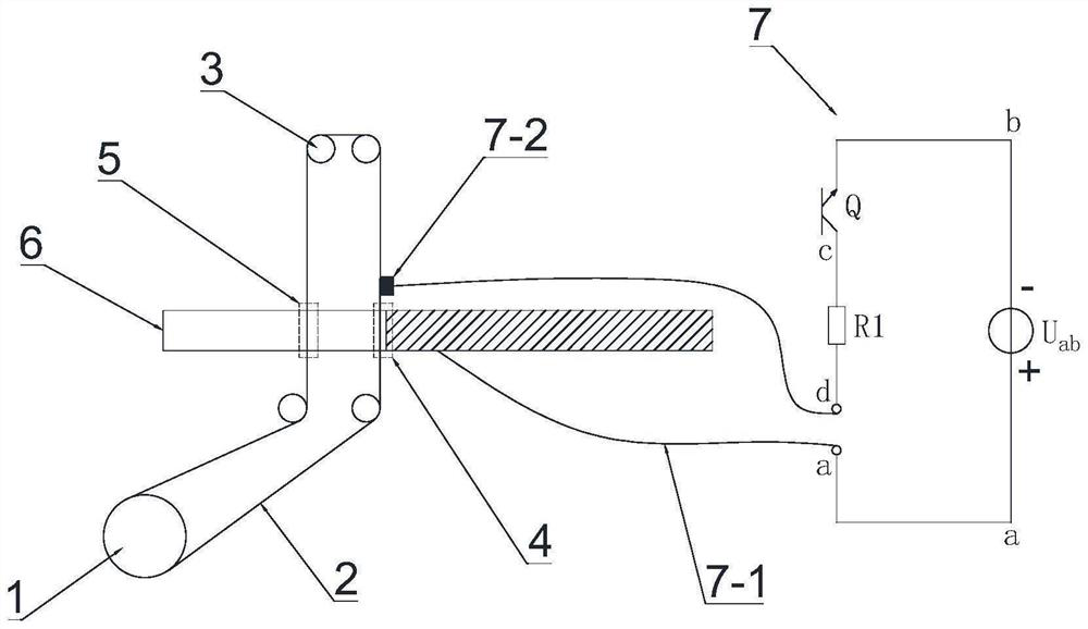
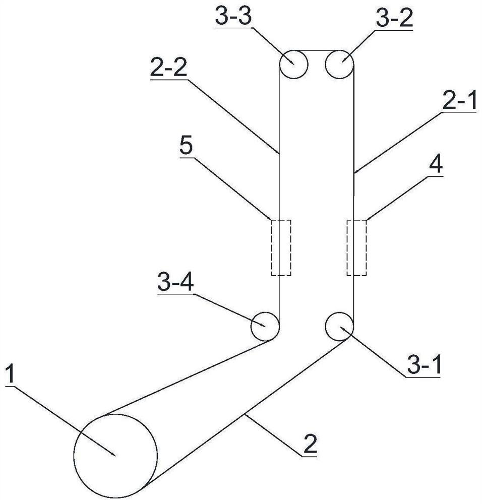
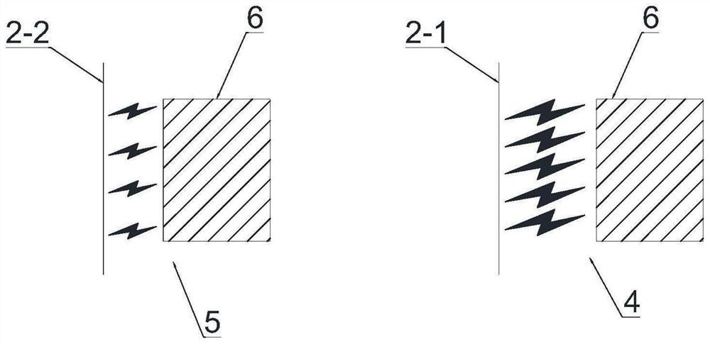
[0058] Other specific structures in this embodiment are the same as those in Embodiment 1, the difference is that the number of the electrode wire segments is three segments and other numbers. When the number is three segments, the electrode wire with the largest passing current is Section 2-1 is the rough machining electrode wire section, and the remaining two electrode wire sections with smaller passing current are the finishing wire section 2-2. The smaller the passing current, the higher the machining accuracy; the farther the electrode wire section is from the DC power supply Negative U ab , the smaller the passing current. By adopting the above structure, the processing method of "cutting one and repairing two" can be realized. The second finishing current will also be smaller than the first finishing current. The size of the processing current is the same as the length of the electrode wire 2 (resistance) between the parallel electrode wire segments. value) related.

Embodiment 3

[0060] see Figure 7, the other specific structures in this embodiment are the same as those in Embodiment 1, the difference is that the guide wheel assembly 3 further includes a godet wheel 3-5, the The electrode wire 2 passes through the first threading wheel 3-1, the first capstan 3-2, the godet 3-5, the second capstan 3-3 and the second capstan in sequence. The wire wheel 3-4 is finally rewound to the wire drum 1; by setting the wire godet 3-5, the electrode wire 2 between the parallel electrode wire segments can be ensured to have sufficient length; at the same time, the guide wheel assembly 3 can be become more compact.

Embodiment 4

[0062] Other specific structures in this embodiment are the same as those in Embodiment 1, except that a constant value resistor can be connected between the rough machining wire electrode segment 2-1 and the finishing wire electrode wire segment 2-2, thereby changing the The current size of the finishing wire electrode segment 2-2.


PUM


Abstract

The invention discloses a wire cut electrical discharge machining device and method capable of conducting rough machining and finish machining synchronously, the device comprises a wire winding drum, an electrode wire and a guide wheel assembly, and the electrode wire wound on the wire winding drum passes through the guide wheel assembly and is finally wound back to the wire winding drum; wherein the guide wheel assembly divides the electrode wire into at least two electrode wire sections which are parallel to each other; and currents passing through the electrode wire sections are different in magnitude. According to the device, rough machining and finish machining can be synchronously carried out on a workpiece, high dimensional precision and low surface roughness are ensured, and the machining efficiency is greatly improved; in addition, errors caused by repeated positioning of the workpiece are avoided, and the machining precision is further improved.

Description

technical field [0001] The invention relates to the technical field of electrical discharge machining, in particular to a wire electrical discharge cutting device and method for synchronously performing roughing and finishing. Background technique [0002] EDM is to connect the tool electrode and the workpiece to the two poles of the pulse power supply respectively, and immerse them in the working fluid, or charge the working fluid into the discharge gap. The tool electrode is controlled to feed to the workpiece through the gap automatic control system. When the gap between the two electrodes reaches a certain distance, the pulse voltage applied to the two electrodes will break down the working fluid and generate spark discharge. A large amount of thermal energy is instantaneously concentrated in the micro-channel of the discharge, the temperature can be as high as more than 10,000 degrees Celsius, and the pressure also changes sharply, so that the local trace metal material...

Claims


Application Information

Patent Timeline
Patent Type & Authority Applications(China)
IPC IPC(8): B23H7/02B23H7/10B23H11/00
CPCB23H7/02B23H7/105B23H11/00Y02P70/10
Inventor 苏国康张永俊李佳旺钟紫鹏
Owner GUANGDONG UNIV OF TECH
Features
  • R&D
  • Intellectual Property
  • Life Sciences
  • Materials
  • Tech Scout
  • Unparalleled Data Quality
  • Higher Quality Content
  • 60% Fewer Hallucinations
Learn More