Speed real-time tracking hydraulic control method, control system and engineering machinery

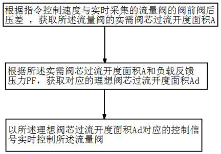
A hydraulic control system and real-time tracking technology applied to construction machinery. , Speed ​​real-time tracking hydraulic control system, speed real-time tracking hydraulic control field, can solve the problems that cannot be effectively solved, the control accuracy of the luffing balance valve is reduced, and the opening pressure of the luffing balance valve 4a is increased, so as to facilitate large-scale application and speed tracking accuracy. High, working smoothness improvement effect

Pending Publication Date: 2022-08-09
ZOOMLION HEAVY IND CO LTD
View PDF8 Cites 2 Cited by
  • Summary
  • Abstract
  • Description
  • Claims
  • Application Information

AI Technical Summary

Problems solved by technology

However, the variable amplitude speed is completely controlled by the pilot oil hydraulic pressure to adjust the opening of the main valve core by experience, the speed cannot be accurately controlled, and the swing is serious
When the traditional gravity drop system is used to control the speed of the variable-amplitude drop, it has the following disadvantages: First, the speed during the variable-amplitude drop cannot be accurately controlled. Long-term hand operation is prone to fatigue and risks
Second, the opening pressure of the spool of the luffing balance valve increases with the increase of the load. Therefore, when the boom is falling, the opening pressure of the luffing balance valve 4a also increases due to the increase of the load. This will cause the pressure of the pilot hydraulic control oil to also increase, and the control signal of the pilot handle that controls the pressure of the pilot hydraulic control oil needs to gradually increase
However, under normal circumstances, the minimum control signal of the pilot handle is set to a fixed value, which will cause the minimum output control signal of the pilot handle to be higher than the opening control pressure of the luffing balance valve 4a when the load is low (such as when the boom is at a large elevation angle). There is an impact at the moment of falling amplitude; when the load is high (such as when the boom is at a small angle), the minimum output control signal of the handle is lower than the opening control pressure of the balance valve, the dead zone of the handle control increases, the effective stroke decreases, and the control accuracy of the luffing balance valve decreases
Third, in essence, the drop speed of the traditional boom luffing system is adjusted by the operator based on experience to adjust the input current of the electric proportional valve in the pilot control oil circuit, and control the pilot oil pressure of the luffing balance valve 4a to control the opening of the spool , so as to adjust the flow through the oil cylinder to achieve the purpose of changing the falling speed. The speed is not easy to control during the falling process and has high requirements for the machine operator.
[0005] In fact, the above-mentioned problems are common in the application of engineering machinery where the balance valve is used to control the working stability of the hydraulic actuators. However, in view of the complexity of hydraulic control and the variability of working conditions, the above-mentioned defects have not been solved in this field. Effectively solve the problem, resulting in unsatisfactory smoothness of work, and even lead to safe operation accidents

Method used


Image

  • Speed real-time tracking hydraulic control method, control system and engineering machinery
  • Speed real-time tracking hydraulic control method, control system and engineering machinery
  • Speed real-time tracking hydraulic control method, control system and engineering machinery

Examples


Embodiment Construction

[0048] The specific embodiments of the present invention will be described in detail below with reference to the accompanying drawings. It should be understood that the specific embodiments described herein are only used to illustrate and explain the present invention, and the protection scope of the present invention is not limited to the following specific embodiments. .

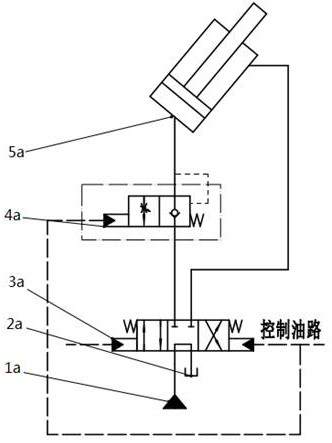
[0049] Since the core technical concept of the present invention itself has a logical level progression and technical complexity, in order to help the understanding of the present invention, the following first takes the boom luffing hydraulic control system of a truck crane as an example, and the core technical concept of the present invention is applied in specific applications. Examples are described in detail. On the basis of fully understanding the control logic and technical concept of the present invention through this typical application example, the control concept of the present invention is not ...


PUM


Abstract

The invention discloses a speed real-time tracking hydraulic control method, a speed real-time tracking hydraulic control system and engineering machinery, and the speed real-time tracking hydraulic control method adjusts the working medium flow of a hydraulic execution element based on a flow valve, the speed real-time tracking hydraulic control method comprises the following steps that according to the instruction control speed and the valve front and rear pressure difference delta P, collected in real time, of a flow valve, the actually-needed valve element overflowing opening area A of the flow valve is obtained; on the basis of the actually-needed valve element overflowing opening area A and the load feedback pressure PF, the actually-needed valve element overflowing opening area A is corrected according to the corresponding relation, and therefore the corresponding ideal valve element overflowing opening area Ad is obtained; and the flow valve is controlled in real time by a control signal corresponding to the ideal valve core overflowing opening area Ad. According to the invention, the speed control of the hydraulic actuator can be automatically realized, the automation degree of speed control is improved, the interference of human factors on the control process can be avoided, the control accuracy is improved, and the jogging stability is improved.

Description

technical field [0001] The invention relates to a speed control method for a hydraulic actuator, in particular to a hydraulic control method for speed tracking in real time. Further, the present invention relates to a corresponding speed tracking hydraulic control system in real time. In addition, the present invention also relates to a construction machine. Background technique [0002] Hydraulic actuators (typically hydraulic cylinders or hydraulic motors) are commonly used in construction machinery to drive the working mechanism. The smoothness of the movement of the working mechanism and the precision of fretting under fine operation are very important to the working quality of the working mechanism. In the working mechanism of some construction machinery, such as the hoisting and unwinding mechanism driven by hydraulic motor, the boom luffing mechanism of truck crane, etc., if the speed control of hydraulic actuator lacks stability, it will seriously affect the safety ...

Claims


Application Information

Patent Timeline
Patent Type & Authority Applications(China)
IPC IPC(8): F15B13/02F15B13/044F15B21/02B66C13/20B66C23/82B66D1/44
CPCF15B13/02F15B13/044F15B21/02B66C13/20B66C23/82B66D1/44F15B2211/6336F15B2211/6306Y02E10/20
Inventor 王维付玲张军花尹莉刘延斌陈锋黄赞吴斌张玉柱
Owner ZOOMLION HEAVY IND CO LTD
Why Eureka
Try Eureka