
Heat exchanger

A heat and heat dissipation unit technology, applied in the field of heat exchangers, can solve the problems of complex structure, difficult lightweight structure, complex heat exchanger structure, etc., and achieve the effects of low manufacturing cost and high bending rigidity

Inactive Publication Date: 2004-07-07
HONDA MOTOR CO LTD +1
View PDF1 Cites 0 Cited by
  • Summary
  • Abstract
  • Description
  • Claims
  • Application Information

AI Technical Summary

Problems solved by technology

The pair of water tanks are made of thick walls and provided with reinforcements whose two ends are respectively connected to the upper and lower ends of the pair of water tanks to strengthen the heat exchanger, which makes the structure of the heat exchanger complicated. Difficult to be made into lightweight structures
Since the heat exchanger is a distance away from the internal combustion engine which vibrates considerably, the cooling water system needs to use long pipes, resulting in a complicated structure, and a heavy load is added to the water pump of the cooling water system

Method used


Image

  • Heat exchanger
  • Heat exchanger
  • Heat exchanger

Examples


Embodiment Construction

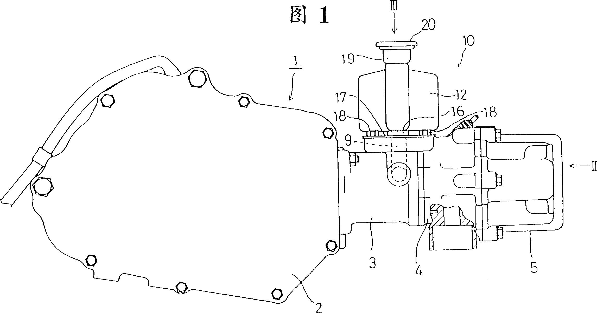
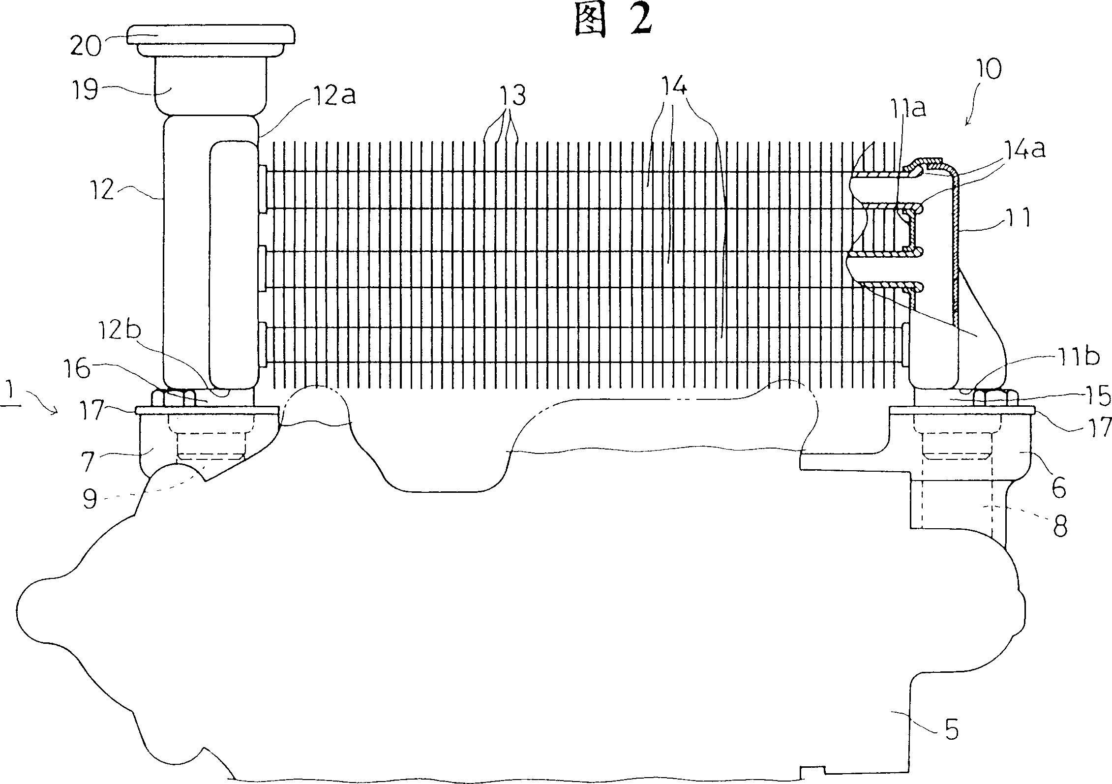
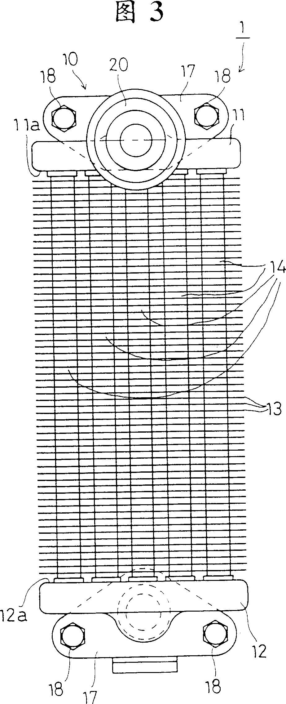
[0017] A heat exchanger according to a first embodiment of the present invention will now be described with reference to FIGS. 1 to 3. FIG. A four-stroke cycle, single-cylinder water-cooled internal combustion engine (hereinafter referred to simply as "water-cooled internal combustion engine") 1 is mounted on a small motorcycle including two wheels, three wheels or four wheels for uneven land. The water-cooled internal combustion engine 1 has a split crankcase 2 , a cylinder block 3 , a cylinder head 4 and a cylinder head cover 5 . A cylinder block 3 is attached to the front end of the crankcase 2, the central axis of a cylinder hole (not shown) made in the cylinder block 3 extends longitudinally substantially horizontally, and the cylinder head 4 and the cylinder head cover 5 are assembled in this order. Placed on the front end of the cylinder block 3, the cylinder block 3, the cylinder head 4 and the cylinder head cover 5 are all fastened on the crankcase 2. The cylinder bl...


PUM


Abstract

A heat exchanger is connected directly or through connecting members to a water-cooled internal combustion engine. The heat exchanger comprises a heat radiating unit comprising a plurality of round cooling water tubes of a circular cross section and plate-shaped heat radiating fins fixed to and longitudinally arranged on the cooling water tubes at intervals, and a pair of tanks disposed on the opposite sides of the heat radiating unit, respectively, and joined to the opposite ends of the plurality of cooling water tubes.

Description

technical field [0001] The invention relates to a heat exchanger for use with a water-cooled internal combustion engine. Background technique [0002] Recently, a water-cooled internal combustion engine employs a lightweight corrugated-fin radiator, such as the heat exchanger disclosed in Japanese Patent No. JP-U 58-93678. This prior art corrugated-fin heat sink has an enormous heat dissipation capacity, ie, the amount of heat released per unit cooling air passage area. This prior art corrugated fin radiator is structured like this: a pair of opposite water tanks are connected with a plurality of flat cooling water pipes, and these water pipes extend horizontally, and their flat surfaces are all in the horizontal plane , and arranged in layers in the vertical direction, and then the corrugated fins are connected to each flat cooling water pipe. This corrugated fin type cooling water pipe is easy to bend, and the corrugated fins are easily deformed. Thus, the strength and ...

Claims


Application Information

Patent Timeline
IPC IPC(8): B62J99/00F01P3/02F01P3/04F01P3/18F01P11/04F01P11/10F28D1/04F28D1/053F28F9/00F28F9/02F28F13/00
Inventor 深町昌俊厚木英夫
Owner HONDA MOTOR CO LTD
Features
  • Generate Ideas
  • Intellectual Property
  • Life Sciences
  • Materials
  • Tech Scout
  • Unparalleled Data Quality
  • Higher Quality Content
  • 60% Fewer Hallucinations
Learn More