
Airflow jetting equipment for drying slurry and paste

A technology of jet airflow and drying treatment, which is applied in the direction of drying solid materials, lighting and heating equipment, heating to dry solid materials, etc., can solve the problems of time-consuming, large loss of organic components of sludge, and high energy consumption, etc. The effect of advanced economic indicators, easy large-scale operation, and wide adaptability

Inactive Publication Date: 2004-07-07
周立秋
View PDF0 Cites 1 Cited by
  • Summary
  • Abstract
  • Description
  • Claims
  • Application Information

AI Technical Summary

Problems solved by technology

[0003] At present, there are mainly two methods for sludge in China: one is to dry naturally, that is, to accumulate in an open area; the other is to make sludge compost, to mix and accumulate sludge with urban garbage, straw, etc., to make it ferment , and then used as agricultural fertilizer, the disadvantages of the above method are that it takes a long time, takes up a lot of land, is labor-intensive, and pollutes the environment and groundwater. The fertilizer formed cannot be packaged, is not easy to transport, and cannot form a commodity
[0004] At present, some people in China try to dry the sludge, but the disadvantages are high energy consumption, uneven drying, and the loss of organic components in the dried sludge, so it is not easy to meet the needs of the market.

Method used


Image

  • Airflow jetting equipment for drying slurry and paste
  • Airflow jetting equipment for drying slurry and paste

Examples


Embodiment Construction

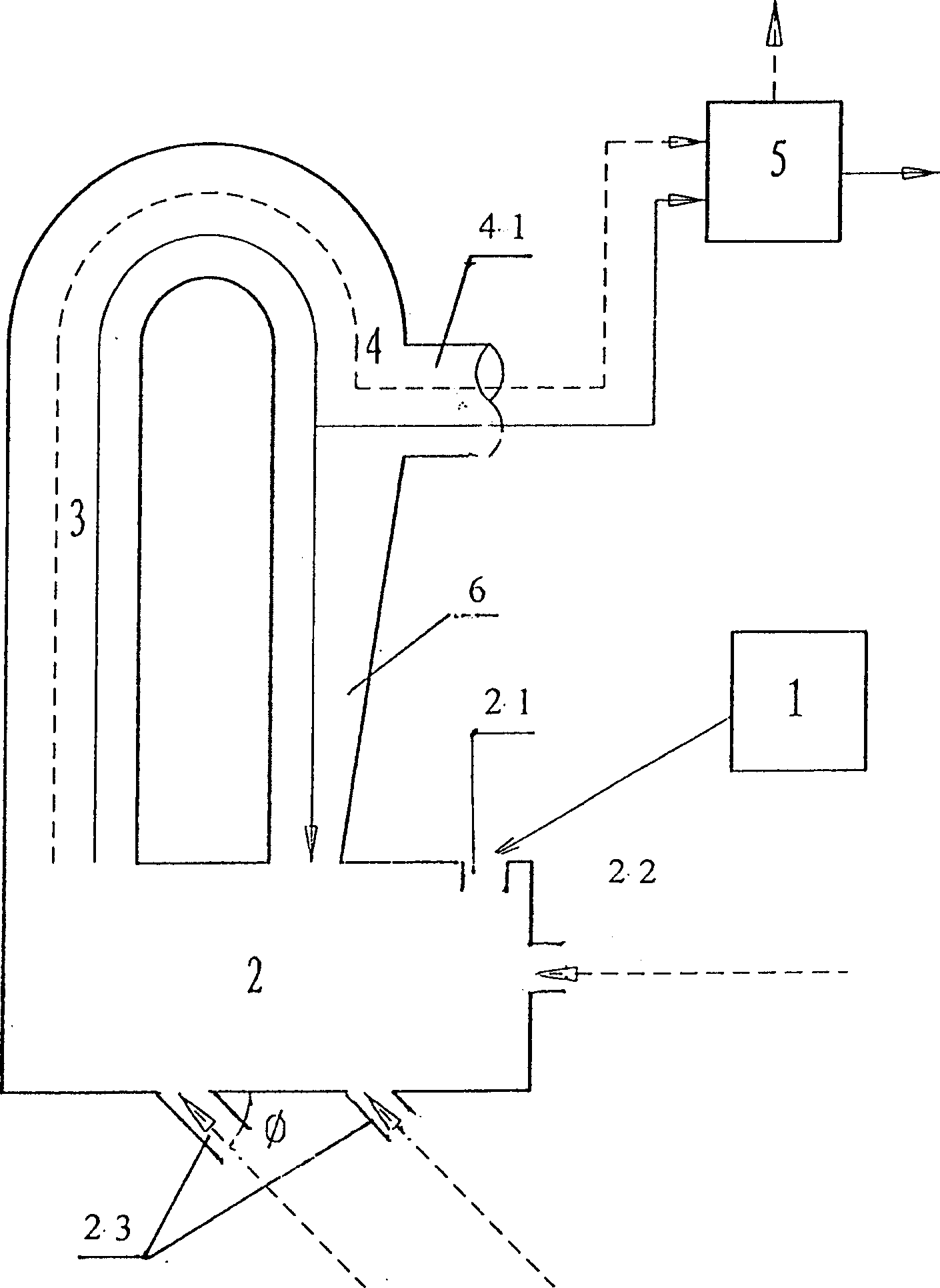
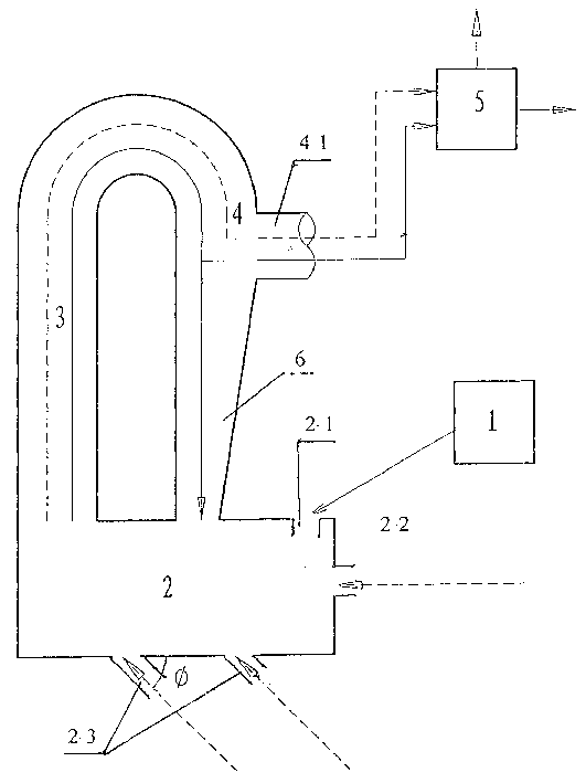
[0020] As shown in Figure 1: the main body of the dryer is composed of a crushing and drying chamber 2, a gas-solid conveying pipeline 3, a gas-solid coarse separator 4, a gas-solid coarse separation outlet 41 and a gas-solid separation system 5 connected thereto. The solid conveying pipe 3 and the gas-solid coarse separator 4 are actually an inverted U-shaped pipe, the lower opening of which communicates with the crushing and drying chamber, the vertical pipe 3 away from the material inlet serves as the gas-solid conveying pipe, and the vertical pipe near the material inlet The pipe is used as a material return port, and its upper end is provided with a gas-solid coarse separation outlet 41 to communicate with the gas-solid separation system. Due to gravity and the direction of the gas-solid coarse separation outlet forms a certain angle with the vertical pipe on the side of the pipe, so that this area A gas-solid rough separator (zone) is formed. The hot air medium introduce...


PUM


Abstract

A jet fluid and paste material drying treatment apparatus comprises a feed conveying system, a disintegrating-drying chamber, a gas-solid two-phase delivery separating system. The rough separating is conducted in the reverse U-shaped tube set at the upper part of the disintegrating-drying chamber connected to the lower mouth of the reverse U-shaped tube. The vertical tube, far from the material feed mouth, of the reverse U-shaped tube is used as gas-solid delivery tube, and the vertical tube, near to the material feed mouth, is used as material return mouth. At the upper part of said vertical tube near to the material feed mouth is provided wiht a gas-solid rough separation region with an outlet connected to the gas-solid separation system.

Description

technical field [0001] The invention relates to a jet air slurry and paste material drying treatment equipment, in particular to a drying treatment equipment for sludge deposited after sewage treatment and lake silt. Background technique [0002] In my country, sewage treatment, especially urban sewage treatment, has just started, and the quantity and scale are small, and the sludge settled after sewage treatment is seldom retreated. If this sludge is not treated, it will cause secondary pollution to the environment and groundwater. But this kind of sludge contains a lot of organic components. If it is treated and utilized, it can become a good organic fertilizer and has many advantages. And after the sludge is dried, it can also be used as raw materials for fuel, building materials products, papermaking and other industries. [0003] At present, there are mainly two methods for sludge in China: one is to dry naturally, that is, to accumulate in an ...

Claims


Application Information

Patent Timeline
Patent Type & Authority Patents(China)
IPC IPC(8): F26B3/12
Inventor 周立秋
Owner 周立秋
Learn More