Pulse power source for high-energy accelerator

A technology of pulse power supply and accelerator, which is applied in the direction of electric pulse generator circuit, energy storage components to generate pulses, electrical components, etc., can solve the problem of high additional energy consumption, and achieve the effects of reduced cost, simple circuit and small space occupation

Inactive Publication Date: 2004-09-22
UNIV OF SCI & TECH OF CHINA
View PDF0 Cites 0 Cited by
  • Summary
  • Abstract
  • Description
  • Claims
  • Application Information

AI Technical Summary

Problems solved by technology

[0005] The above-mentioned fast and slow pulse power supplies all require high-voltage power supply (the high voltage required by the changing current on the inductive load needs to be provided by an external power supply), which makes the additional energy consumption very high

Method used


Image

  • Pulse power source for high-energy accelerator
  • Pulse power source for high-energy accelerator
  • Pulse power source for high-energy accelerator

Examples


Embodiment 1

[0032] Embodiment 1: belongs to slow pulse power supply

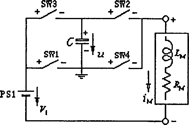
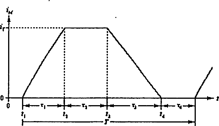
[0033] Design requirements: The load is powered by 40 two-pole magnets in series, with a total inductance of 0.756H and a total resistance of 1.232Ω. The current waveform is a triangle wave with a flat bottom of about 30A or a zero flat bottom. The rise time of the triangle wave is 0.45 seconds, the fall time is less than or equal to 0.45 seconds, the peak current is 694.2A, and the duty cycle is 1 second.

[0034] Main components of the system: (1) The main components of the zero-flat-bottom solution include: an energy storage capacitor bank, a DC regulated power supply, two IGBT modules and five diodes (see Figure 8). (2) 30A flat-bottom solution: add a DC stabilized power supply and a switch (see Figure 9).

[0035] ① Energy storage capacitor bank: take the capacitance value of 320mF, divide it into two groups, each group is 160mF, and form a series-parallel circuit with three diodes. The model of SIEMENS company is...

Embodiment 2

[0036] Embodiment 2: belongs to slow pulse power supply

[0037] Design requirements: load inductance L M =1.1H, load resistance R M =0.75Ω; the load current waveform is a trapezoidal wave, where: flat-bottom current i B =200A, flat top current i T =2850A, rise time τ 1 =0.79s, flat top time τ 2 =2s, duty cycle T=4s.

[0038] The main components of the system include: an energy storage capacitor bank, three DC regulated power supplies, two sets of IGBT assemblies, a series-connected SCR assembly and two diode assemblies (see Figure 7). The main technical parameters are as follows:

[0039] ① Energy storage capacitor bank: Electrolytic capacitors are used, the capacitance value is 2F, and the charging voltage is 3061V. Choose the product of SIEMENS company model B 43 456 (or B 43 458), 12000μ / 450V (size 91.0×221.0), a total of 8183 (7 strings×1169 parallel). ②DC power supply: 150-160V / 200A for PS0, 760-790V / 2880A for PS1, 1360-1380V / 2880A for PS2. ③ IGBT combination m...

Embodiment 3

[0040] Embodiment three: it belongs to the fast pulse power supply.

[0041] Design requirements: load inductance 1.1μH, resistance 10mΩ. The current waveform is a trapezoidal wave with zero flat bottom, the flat top value is 4000A, the pulse width is 4 microseconds, the flat top width is 0.3 microseconds, and the duty cycle is 1 second.

[0042] This power supply has the particularity that the pulse is very narrow and the period is very long. In order to reduce the current supplied by the DC stabilized power supply during the pulse, use a capacitor C 0 , Charging resistor R 0 The combination with the DC stabilized power supply PS1 replaces PS1 in the basic schematic diagram, that is, the positive output terminal of PS1 is connected to the charging resistor R 0 one end of the R 0 the other end of the C 0 On the "+" terminal of PS1, the negative output terminal of PS1 is connected to C 0 On the "-" end (see accompanying drawing 10). In this way, during the pulse the syst...


PUM


Abstract

The present invention relates to a power supply device for high-energy accelerator or other equipment having need of producing impulse strong magnetic field, including main circuit and auxiliary circuit, and is characterized by that its main circuit is formed from D.C. voltage regulation power supply, energy-storing capacitor and electronic switch, and the flat bottom and flat top of impulse current can be provided by D.C. voltage regulation power supply, and its rising and falling can be produced by energy-storing capacitor and load inductance resonance oscillation. Said invention utilizes proper combination of electronic switch to implement conversion of every stage, also can adopt capacitor series-parallel circuit to shorten the falling and rising time of impulse current.

Description

technical field [0001] The invention relates to a power supply device for a high-energy accelerator or other equipment that needs to generate a pulsed strong magnetic field. Background technique [0002] The pulse power supply in the high-energy accelerator is divided into two types: slow pulse power supply and fast pulse power supply: the slow pulse power supply is used to supply power to the main magnet of the synchrotron, and the fast pulse power supply is used to inject impact magnets and cutting in the extraction system of various high-energy accelerators Magnet powered. [0003] At present, there are two traditional types of slow pulse power supply: one is the resonant power supply device [see: A.Yong and B.E.shafer, "Electrical Characteristics of the SSC Low-Energy Booster Magnet System", Conference Record IEEE, Particle Accelerator Conference, pp.1285-1287, 1993], its structure is that a DC power supply provides DC bias current through a choke coil connected in seri...

Claims


Application Information

Patent Timeline
Patent Type & Authority Patents(China)
IPC IPC(8): H03K3/53H05H7/04
Inventor 张云祥董赛董晓莉赵涛张海燕姚成贵
Owner UNIV OF SCI & TECH OF CHINA
Why Eureka
Try Eureka