Percolation water intaking method of new engineering structure

A technology of engineering structure and infiltration, applied in chemical instruments and methods, water supply devices, drinking water devices, etc., can solve the problems of limited water intake area control range, high engineering cost, water inrush, etc. The effect of low degree of mechanization and avoiding potential safety hazards

Inactive Publication Date: 2006-02-01
重庆泓源渗滤取水科技有限公司
View PDF1 Cites 3 Cited by
  • Summary
  • Abstract
  • Description
  • Claims
  • Application Information

AI Technical Summary

Problems solved by technology

In April 1978, the "Hydrogeological Handbook" of Geological Press and the "Handbook of Water Supply and Drainage Design Volume 3" of China Architecture Press in 1996 introduced the radiation well structure. For the loose accumulation layer in the direction, the water intake and collection are carried out by manually driving into the steel pipe with holes with a maximum length of no more than 50m; it is only suitable for the exploitation of groundwater in loose medium and coarse sand accumulation layers, and the control of the water intake area Limited scope, cannot improve the quality of source water taken
The natural filter bed seepage well is a Chinese invention patent (ZL93110953.1) authorized and announced on February 12, 1997. It is composed of radiated seepage holes in the sand and pebble layer; it expands the water intake range of the large well on the basis of the radiation well, and can collect the sand and pebble layer in the lower part of the river and underground subsurface water. The water quality is also better than the radiation well, but this natural filter The bed seepage well has the following main technical defects: because it has river bottom tunnels and branch lanes, it requires high accuracy in survey and design, and the current survey methods cannot fully investigate the geological conditions at the bottom of the river bed (such as the depth of the bedrock). trough), once the survey and design are wrong, there will be serious safety hazards such as water inrush and roof fall during the construction process (there have been many major safety accidents in the actual project to expose the riverbed); and the construction is difficult and the project cost is high, so , this patented technology cannot be popularized and applied on a large scale

Method used


Image

  • Percolation water intaking method of new engineering structure
  • Percolation water intaking method of new engineering structure
  • Percolation water intaking method of new engineering structure

Examples


Embodiment 2

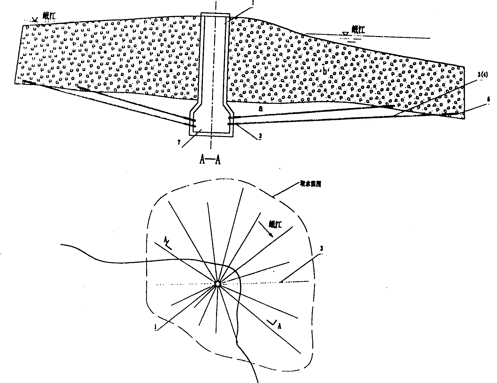
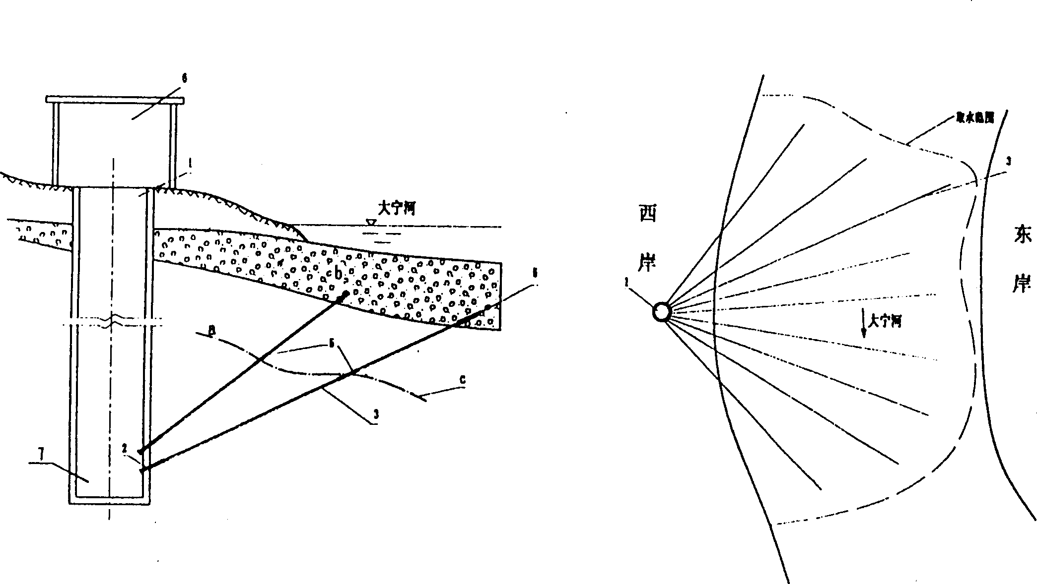
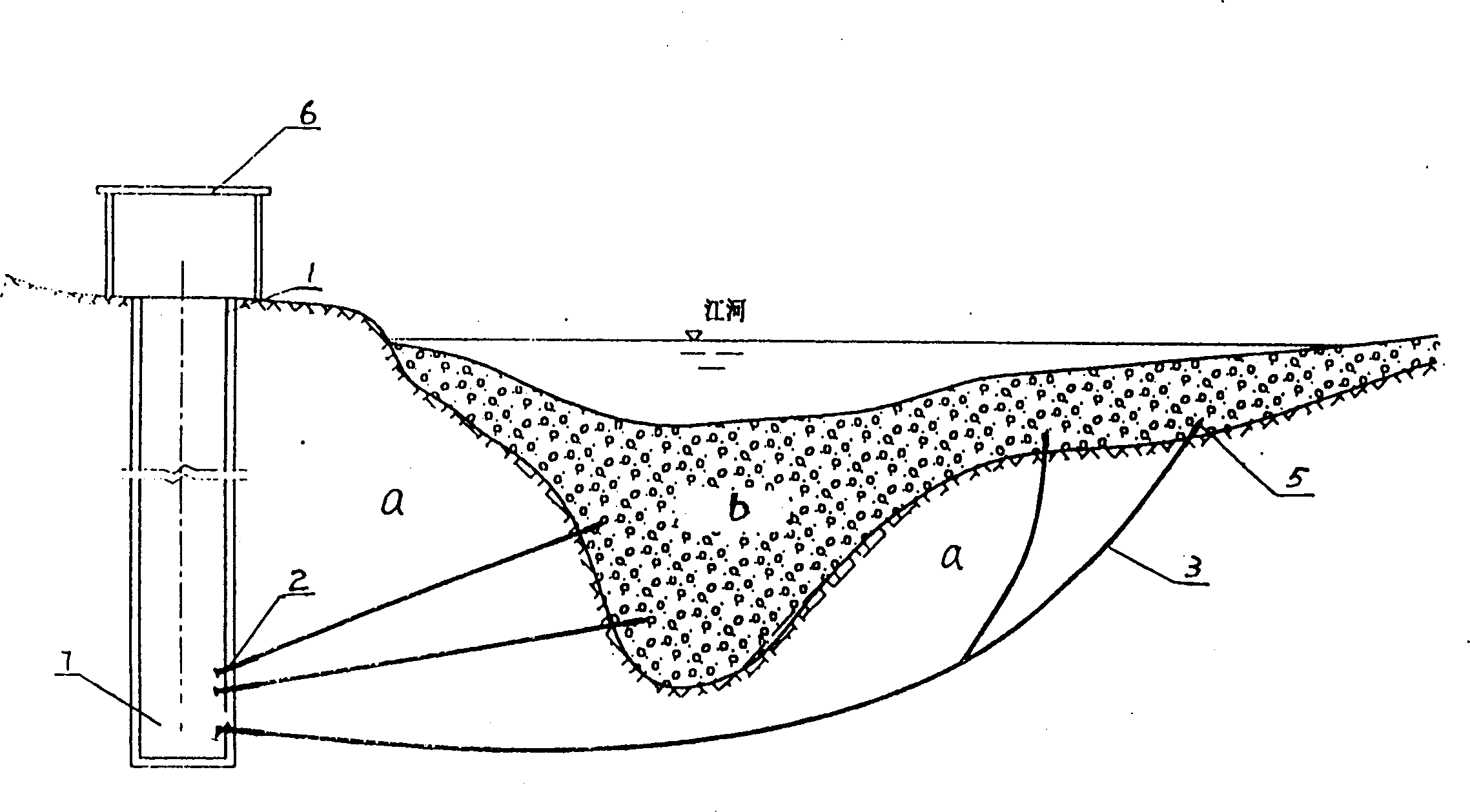
[0026] The present invention's percolation water intake project structure example ( figure 2 )

[0027] The water collection well 1 is built on the bank of the Daning River, and the bottom of the well is embedded in the bedrock a34m through the loose accumulation layer (the total well depth is 46m). Two rows of 12 fan-shaped controlled directional infiltration holes 3 are arranged respectively 2m and 3m away from the bottom of the well to the sand and pebble layer b under the river bed. 2. Due to the good conditions for drilling holes in rock formations, most of them do not adopt synchronous follow-up pipe protection wall, nor do diameter change treatment, so the drilling process is simpler. After the hole is formed, the filter 5 is first placed into the sand and pebble layer from the hole end, and then the filter 5 is installed to infiltrate and ingest the groundwater according to the different water outlet positions of the bedrock cracks c along the way, and is introduced...


PUM

PropertyMeasurementUnit
depthaaaaaaaaaa

Abstract

The present invention relates to underground water taking and collecting method, and is new engineering structure for taking percolation water. The present invention features that the collecting well is embedded into base rock stratum for at least 5 m, controlled directional percolation holes are drilled into grit stratum under the base rock stratum around the well, and filters are set in the hole parts corresponding to the water bearing stratums. The said engineering structure makes the taken underground water need no further processing in the water producing system, and has the merits of both radiation well and natural filtering bed percolation well, including simple engineering structure, being safe and reliable, no damage to ecological environment, etc.

Description

1. Technical field [0001] The invention belongs to methods for water intake and water collection, and in particular to groundwater water intake and water collection methods. 2. Background technology [0002] There are many water intake technologies for groundwater, but the existing technologies that can utilize the natural filtering effect of the formation and have similar technical conditions are the most typical ones are the water intake technology of radiation wells and the water intake technology of natural filter bed seepage wells. In April 1978, the "Hydrogeological Handbook" of Geological Press and the "Handbook of Water Supply and Drainage Design Volume 3" of China Architecture Press in 1996 introduced the radiation well structure. For the loose accumulation layer in the direction, the water intake and collection are carried out by manually driving into the steel pipe with holes with a maximum length of no more than 50m; it is only suitable for the exploitation of gr...

Claims


Application Information

Patent Timeline
Patent Type & Authority Patents(China)
IPC IPC(8): E03B3/11E03B5/04C02F1/00E03B3/06
Inventor 魏民吴德安陈台智
Owner 重庆泓源渗滤取水科技有限公司
Why Eureka
Try Eureka