Method and device for non-contact sealing between rotor and stator

A non-contact, stator technology used in engine sealing, leakage prevention, engine components, etc., can solve problems such as increased friction power and heat generation, and achieve the effects of minimum friction power, improved sealing effect, and low-cost structure

Inactive Publication Date: 2006-02-01
ABB (SCHWEIZ) AG
View PDF0 Cites 0 Cited by
  • Summary
  • Abstract
  • Description
  • Claims
  • Application Information

AI Technical Summary

Problems solved by technology

Downstream of the throttling point, the working fluid must be reaccelerated in the circumferential direction on the rotating parts, so that the frictional power and heat generation in this range increase further

Method used


Image

  • Method and device for non-contact sealing between rotor and stator
  • Method and device for non-contact sealing between rotor and stator
  • Method and device for non-contact sealing between rotor and stator

Examples


Embodiment Construction

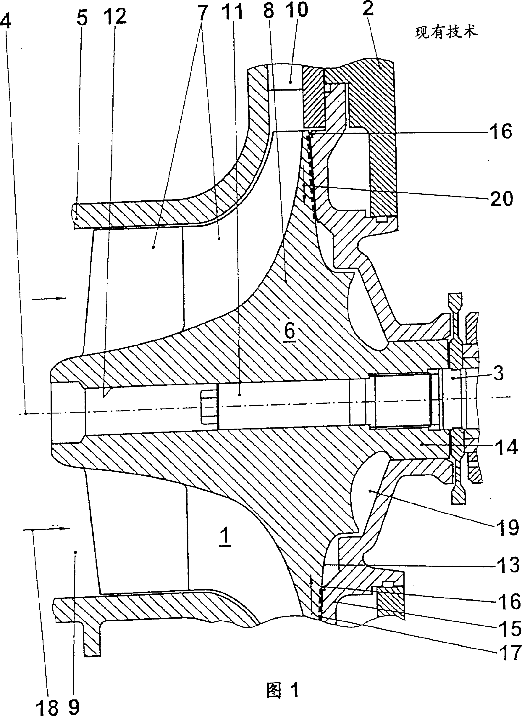
[0022] Only the main components to facilitate the understanding of the invention are shown in the figure, eg the output duct of the working fluid through the labyrinth seal, the turbine side and the support of the turbocharger are not shown. The flow direction of the working medium is indicated by arrows.

[0023] The prior art exhaust gas turbocharger, which is only partially shown in FIG. 1, consists of a centrifugal compressor 1 and an exhaust gas turbine, not shown in the figure, which are supported by a The shafts 3 are connected to each other. The centrifugal compressor 1 of the exhaust gas turbocharger has a machine shaft 4 in the shaft 3 and is equipped with a compressor housing 5 in which a rotor 6 formed as a compressor wheel is rotatable. Connected to axis 3. The compressor wheel 6 has a hub 8 on which a plurality of rotor blades 7 are mounted. A fluid channel 9 is formed between the hub 8 and the compressor housing 5 . Downstream of the rotor blades 7 , a radia...


PUM


Abstract

The object of the invention is to provide an improved method for sealing off the separating gap, formed between a rotor and a stator, in a non-contacting manner, with which method the service life of the components involved can be increased. In addition, an arrangement for carrying out the method is to be shown. According to the invention, this is achieved in that the flow layers, having different circumferential velocities, of the working fluid are divided after the choking action into a first partial flow having a high circumferential velocity and a second partial flow having a low circumferential velocity, the first partial flow is merely deflected, only the second partial flow is swirled and is finally directed parallel to the deflected first partial flow into the latter. To this end, the opposing surface of the choke point is designed as a flow divider for the working fluid. The vortex chamber adjoins the flow divider and is arranged further upstream than the feed duct for the next sealing element.

Description

technical field [0001] The invention relates to a method and a device for carrying out the contactless sealing of a separating gap formed between a rotor and a stator in order to prevent a working fluid from flowing through the separating gap. Background technique [0002] In the manufacture of impeller machinery, in order to seal high-speed rotating parts, labyrinth seals are often used, that is, non-contact seals. Various labyrinth seals are known, the operating principle of which is mostly based on minimizing the fluid-mass flow through the labyrinth seal. For this purpose, labyrinth seals of this type generally provide a plurality of seals of similar construction arranged one behind the other in the flow direction of the working fluid in the separation gap formed between the rotor and the stator to be sealed. Each seal consists of at least one throttling point and a downstream swirl chamber, which more or less clearly characterize the various labyrinth seals. By aligni...

Claims


Application Information

Patent Timeline
Patent Type & Authority Patents(China)
IPC IPC(8): F01D11/02F16J15/447
CPCF01D11/02F16J15/447
Inventor M·伯斯恩M·罗斯J·布雷默U·C·米勒J·格雷伯D·翁德瓦尔德
Owner ABB (SCHWEIZ) AG
Why Eureka
Try Eureka