Pulse width modulator system
A technology of pulse width modulation and signal modulation, applied in the field of pulse width modulator system, can solve the problems of incompatibility and high cost
- Summary
- Abstract
- Description
- Claims
- Application Information
AI Technical Summary
Problems solved by technology
Method used
Image
Examples
Embodiment Construction
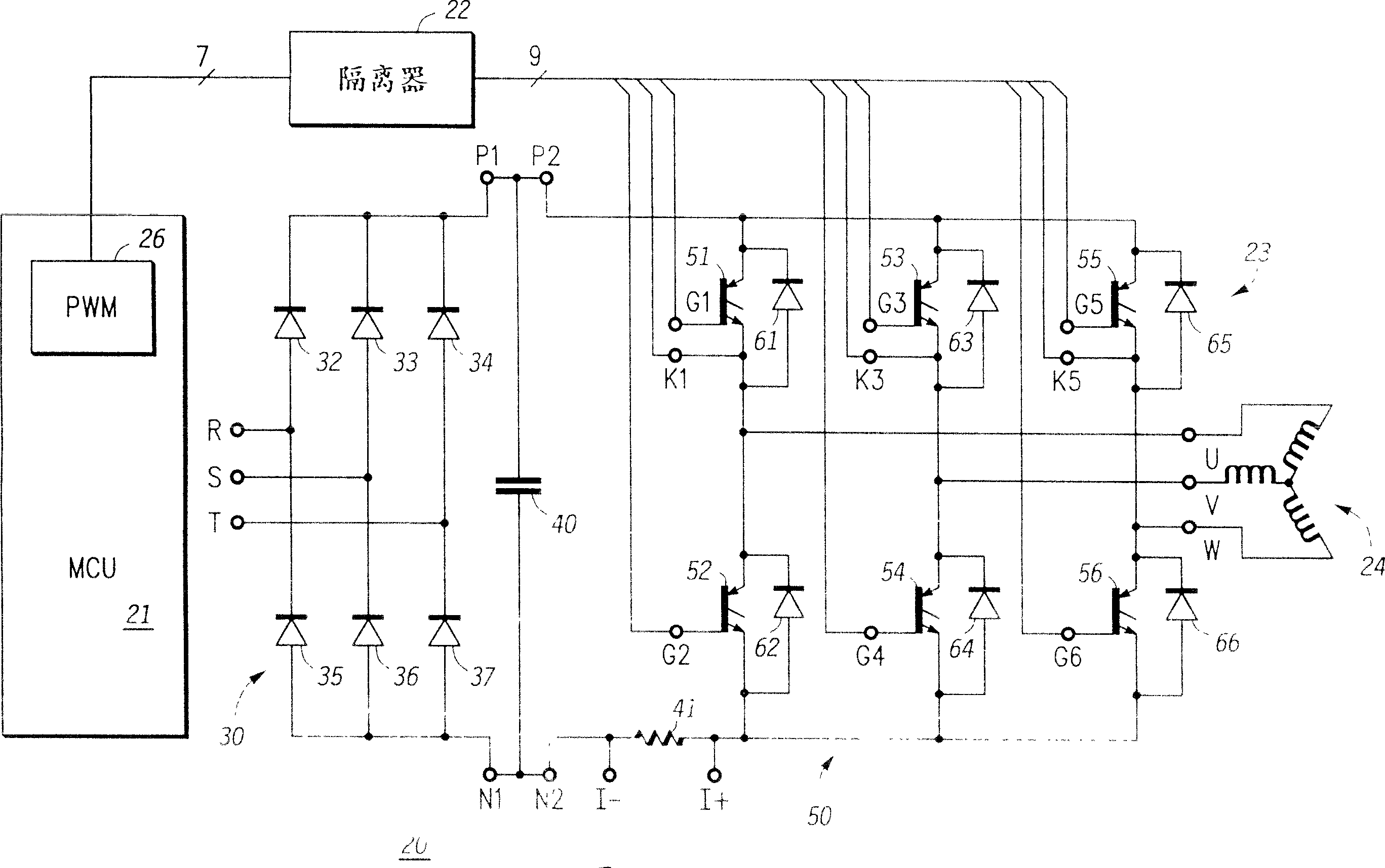
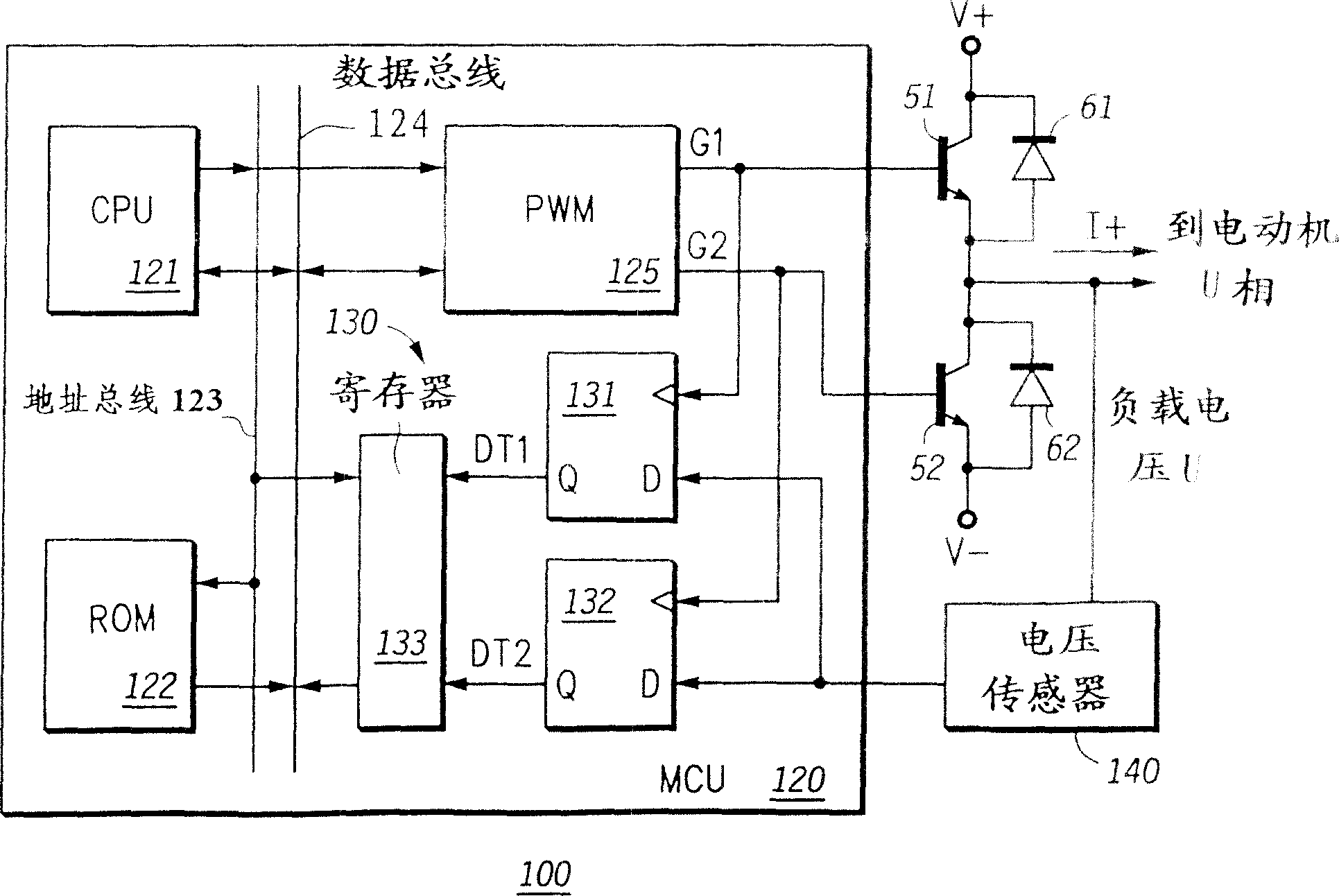
[0023] image 3 A pulse width modulator (PWM) system 100 according to the present invention is shown in part block diagram, part logic diagram and part schematic diagram. It is to be noted that the PWM system 100 does not include all parts of the motor system such as the motor itself, these parts are left out for a better understanding of the invention. PWM system 100 generally includes MCU 120 and voltage sensor 140 . and image 3 Transistors 51 and 52, diodes 61 and 62 are shown having the same reference numerals as corresponding parts in FIG. Transistors 51 and 52 and diodes 61 and 62 are connected to motor U as described in detail in FIG. 1 for connection and operation, which will not be described again here. Note that, for discussion purposes, image 3 The currents marked "I+" in , establish such a rule that a positive current flowing into the U-phase terminal of the motor is represented as a positive value. In addition, the voltage at terminal U is marked as "load volt...
PUM
 Abstract
Description
Claims
Application Information
 - R&D Engineer
- R&D Manager
- IP Professional
- Industry Leading Data Capabilities
- Powerful AI technology
- Patent DNA Extraction
Browse by: Latest US Patents, China's latest patents, Technical Efficacy Thesaurus, Application Domain, Technology Topic, Popular Technical Reports.
© 2024 PatSnap. All rights reserved.Legal|Privacy policy|Modern Slavery Act Transparency Statement|Sitemap|About US| Contact US: help@patsnap.com


