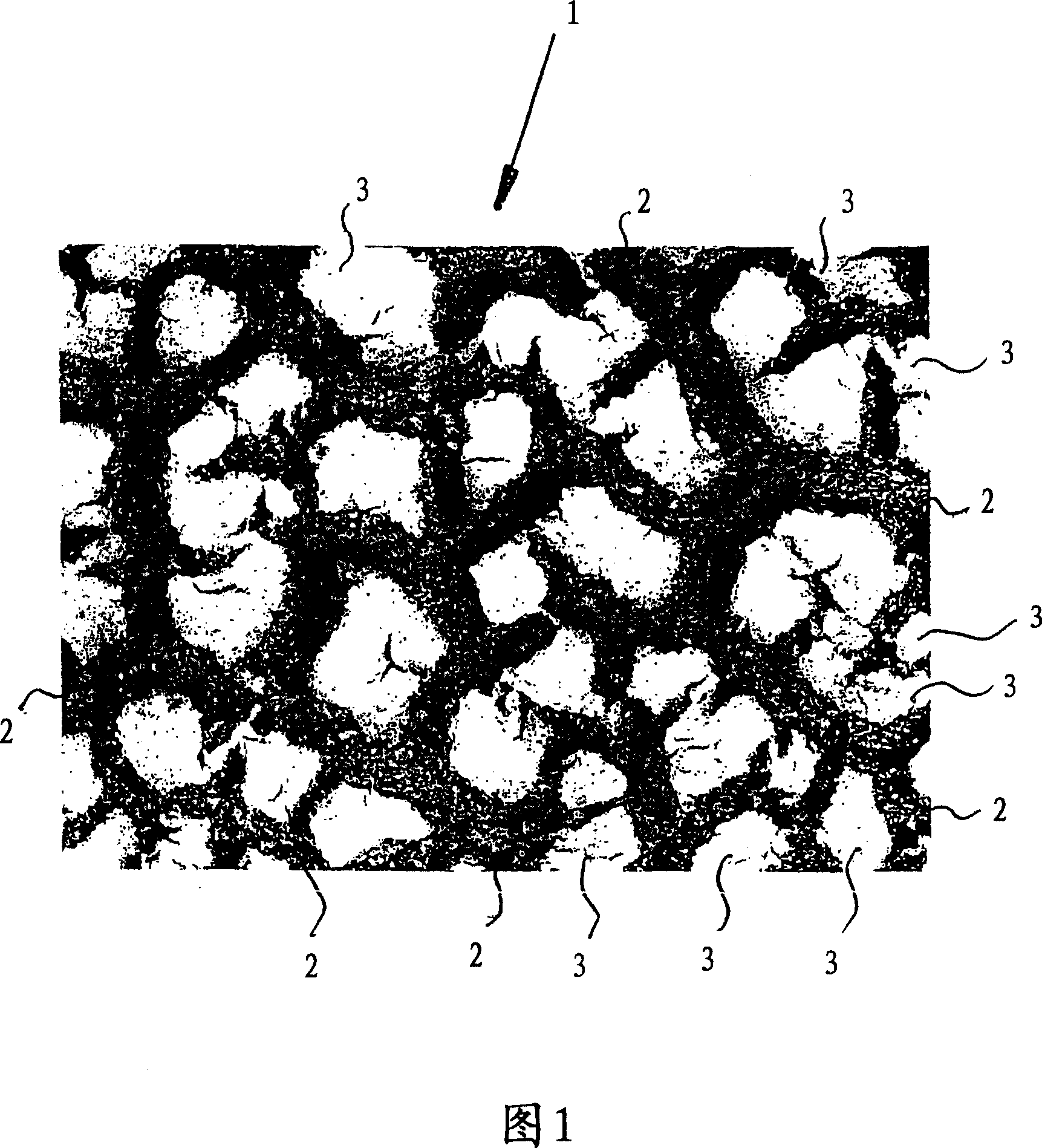
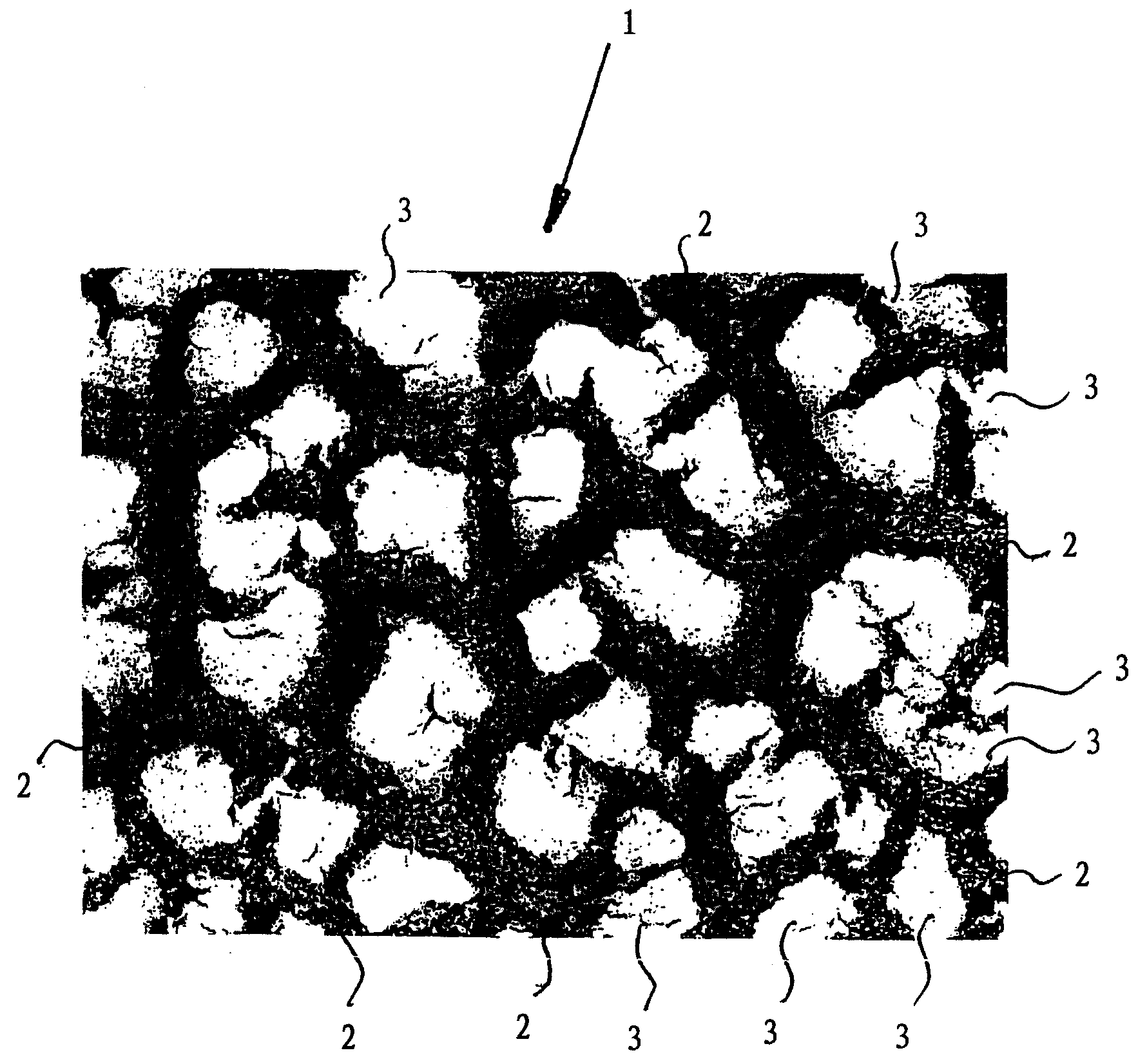
Friction layer running in a medium
A friction layer and friction component technology, applied in friction linings, mechanical equipment, etc., can solve problems such as oil removal, time impact of switching process, and shortened synchronization
- Summary
- Abstract
- Description
- Claims
- Application Information
AI Technical Summary
Problems solved by technology
Method used
Image
Examples
Embodiment 1
[0033] 1. Materials
[0034] Powder: - Iron Oxide Powder (Fe 3 o 4 ), mass 8g,
[0035] - powder, the composition is 30% Mo, 9% Cr, 2.5% Si, the rest is Fe;
[0036] Mass 2g,
[0037] Binder: 2.5% aqueous solution of polyvinylpyrrolidone, volume 16ml.
[0038] 2. Mix the ingredients
[0039] The ingredients were mixed with a mixer for 10 minutes.
[0040]3. Coating
[0041] The mixture is atomized with compressed air and sprayed onto the inner cone of the rotating steel synchronizer ring. The spray thickness is 550 μm. After a drying time of about 5 minutes, the coating has a high green sand strength, which allows good handling of the rings.
[0042] 4. Binder removal, sintering and alignment
[0043] The debinder and sintering process can be performed in one step in the same furnace under hydrogen atmosphere. For this purpose, the furnace is heated at a heating rate of 5 K / min. The debinding process starts at about 300°C and ends at 600°C. The sintering process i...
Embodiment 2
[0061] 1. Materials
[0062] Powder: - Iron Oxide Powder (Fe 3 o 4 ), mass 8.2g
[0063] - graphite powder, mass 1.8g,
[0064] Binder: 2.5% aqueous solution of polyvinylpyrrolidone, volume 16ml.
[0065] 2. Mix the ingredients
[0066] The ingredients were mixed with a mixer for 10 minutes.
[0067] 3. Coating
[0068] The mixture is atomized with compressed air and sprayed onto the inner cone of the rotating steel synchronizer ring. The spray thickness is 700 μm. After a drying time of about 8 minutes, the sprayed coating has a high green sand strength, which allows good handling of the rings.
[0069] 4. Binder removal, sintering and alignment
[0070] The binder removal and sintering processes can be performed in one step in the same furnace under a hydrogen atmosphere. For this purpose, the furnace is heated at a heating rate of 5 K / min. The binder removal process starts at about 300°C and ends at 600°C. The sintering process takes place in the temperature ran...
Embodiment 3
[0087] 1. Materials
[0088] Powder: - copper oxide powder (CuO), mass 8.6g
[0089] - Zinc powder, mass 0.58g
[0090] - Graphite powder, mass 0.82g
[0091] Binder: 2.5% aqueous solution of polyvinylpyrrolidone, volume 16ml.
[0092] 2. Mix the ingredients
[0093] The ingredients were mixed with a mixer for 10 minutes.
[0094] 3. Coating
[0095] The mixture is atomized with compressed air and sprayed onto the inner cone of the rotating steel synchronizer ring. The spray thickness is 680 μm. After a drying time of about 8 minutes, the sprayed coating has a high green sand strength, which allows good handling of the rings.
[0096] 4. Binder Removal, Sintering and Calibration
[0097] The binder removal and sintering processes can be performed in one step in the same furnace under a hydrogen atmosphere. For this purpose, the furnace is heated at a heating rate of 5 K / min. The binder removal process starts at about 300°C and ends at 600°C. The sintering process ta...
PUM
| Property | Measurement | Unit |
|---|---|---|
| particle size | aaaaa | aaaaa |
| thickness | aaaaa | aaaaa |
Abstract
Description
Claims
Application Information
 - R&D
- Intellectual Property
- Life Sciences
- Materials
- Tech Scout
- Unparalleled Data Quality
- Higher Quality Content
- 60% Fewer Hallucinations
Browse by: Latest US Patents, China's latest patents, Technical Efficacy Thesaurus, Application Domain, Technology Topic, Popular Technical Reports.
© 2025 PatSnap. All rights reserved.Legal|Privacy policy|Modern Slavery Act Transparency Statement|Sitemap|About US| Contact US: help@patsnap.com


