Dense wavelength division multiplexer/demultiplexer based on echelle grating

A wavelength division multiplexer and echelle grating technology, applied in the field of optical communication, can solve the problem of not being able to provide a combination of beneficial properties that meet dense wavelength division multiplexing, and achieve the effects of being scalable, cheap, small form factor, and easy to manufacture

Inactive Publication Date: 2002-10-30
JOHN ZINK CO LLC
View PDF6 Cites 5 Cited by
  • Summary
  • Abstract
  • Description
  • Claims
  • Application Information

AI Technical Summary

Problems solved by technology

However, none of these systems provide the beneficial combination of properties necessary to meet the growing demands of DWDM

Method used


Image

  • Dense wavelength division multiplexer/demultiplexer based on echelle grating
  • Dense wavelength division multiplexer/demultiplexer based on echelle grating
  • Dense wavelength division multiplexer/demultiplexer based on echelle grating

Examples


Embodiment Construction

[0035] Specific ways of implementing the invention

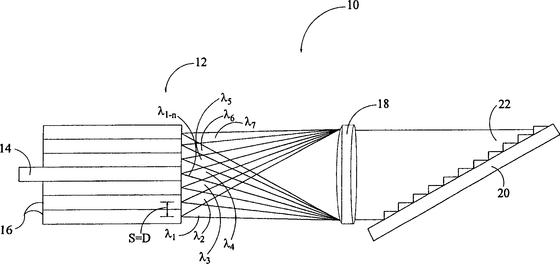
[0036] figure 1 A schematic plan view of a multiplexer / demultiplexer applied in the optical communication system 10 of the present invention is shown. The composition of this multiplexer / demultiplexer includes an outgoing wire bundle 12, and the composition of the outgoing wire bundle 12 includes an input waveguide 14, a plurality of output waveguides 16 arranged in a linear array adjacent to the input optical fiber; a collimating / focusing lens 18 and an echelle grating 20, each of which is optically coupled. In this discussion, multiplexers / demultiplexers will be discussed in terms of demultiplexers. The same description applies to the multiplexer, except that the functions of the input and output waveguides 14, 16 are reversed. Also, for clarity, only seven output waveguides are shown (the center output waveguide is at figure 1 below the input fiber, this can be achieved by Figure 14 See elements 142 and 148 in). Ad...


PUM

PropertyMeasurementUnit
lengthaaaaaaaaaa

Abstract

A dense wavelength division multiplexer / demultiplexer ("DWDM") (10) for use in an optical communication system, comprising a propagating multiple multiplexed with selected channel spacing into a single optical a multiplexed optical waveguide (14) of the optical channel of the signal (λiest; 1-n), a collimation / focusing optical component (18) optically coupled to the multiplexed optical waveguide at a selective focal length, an optically coupled to the collimation / focusing A reflective echelle grating (20) of an optical component (18), wherein the echelle grating (20) has a groove spacing (d) and a blaze angle (θb) capable of providing multiplexed optical signals (λ1- n) of the channel spacing (d). A linear array of single-channel waveguides (16), each propagating a single channel in the near-infrared wavelength region, is optically coupled to collimating / focusing optics, each single-channel waveguide (16) having a center and a propagating termination, and propagating The distance between the terminals and the collimating / focusing optics is equal to the focal length, while the distance between the centers of adjacent branching waveguides is the selected channel spacing (D). Fiber optic harnesses are used to connect the multiplexers operating in the Littrow configuration.

Description

technical field [0001] The present invention relates to optical communications, and more particularly to bulk optical echelle grating multiplexers / demultiplexers in bulk optics. Background technique [0002] In the early days of optical fiber communication, generally one optical fiber was only used to carry a single data channel of a single wavelength. Dense Wavelength Division Multiplexing (DWDM) enables multiple channels of different wavelengths in a given wavelength band to be sent over a single-mode fiber, greatly expanding the amount of data transmitted per fiber. The wavelength of each channel is chosen so that the channels cannot interfere with each other and to minimize the transmission loss of the fiber. A typical DWDM allows up to 40 channels to be transmitted simultaneously over a single fiber. [0003] The amount of data transmitted over fiber optics is increasing exponentially, and capacity for data transmission is depleting rapidly. The cost-effectiveness of...

Claims


Application Information

Patent Timeline
Patent Type & Authority Applications(China)
IPC IPC(8): G02B5/18G02B6/293G02B6/34
CPCG02B5/1861G02B6/29308G02B6/2931G02B6/29361G02B6/29373G02B6/2938
Inventor 安德鲁·萨皮格里·莫菲
Owner JOHN ZINK CO LLC
Why Eureka
Try Eureka