Integrated ice cold-storing machine unit
An ice storage and unit technology, applied in refrigerators, compressors, refrigeration and liquefaction, etc., can solve the problems of many ice storage air conditioning systems, large installation and debugging workload, and high engineering costs, saving installation space and area. , The effect of convenient debugging and shortened construction period
- Summary
- Abstract
- Description
- Claims
- Application Information
AI Technical Summary
Problems solved by technology
Method used
Image

Examples
Embodiment 1
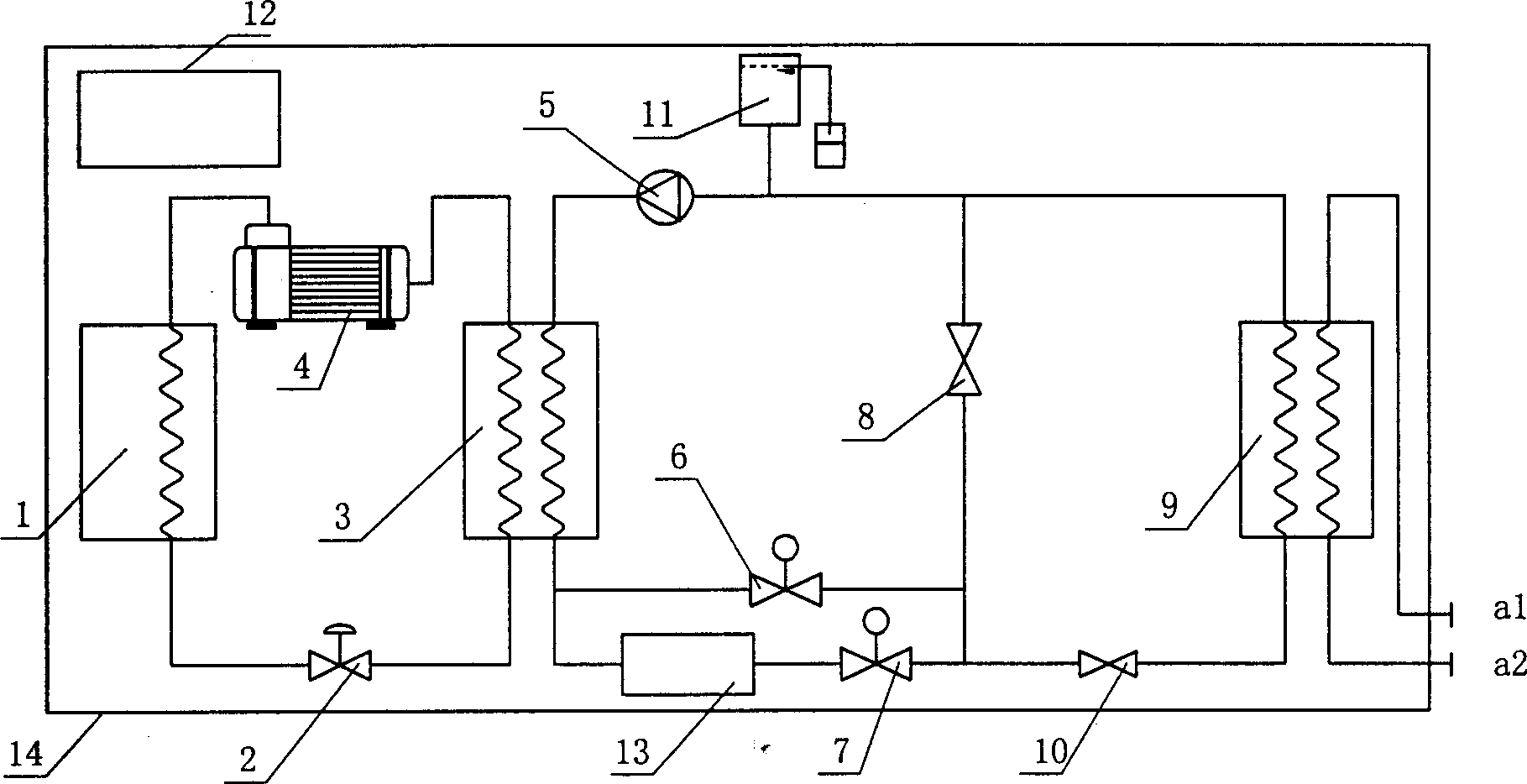
[0032] According to different forms of ice storage systems, ice storage units can be divided into four types: single pump in series, double pump in series, single heat exchanger in parallel and double heat exchanger in parallel. Example 1: An integrated ice storage unit in the form of a single pump in series:
[0033] figure 1 It is the connection diagram of the integrated ice storage unit in the form of series single pump.
[0034] In the refrigerant circuit, the compressor 4, condenser 1, throttling device 2, and evaporator 3 are connected in sequence to form a closed system through refrigerant connecting pipes.
[0035] In the brine circuit, the brine pump 5, the evaporator 3, the electric control valves 6 and 7, the solenoid valves 8 and 10, the heat exchanger 9, the brine expansion tank 11 and the storage tank are connected through the brine connecting pipe. The ice tank body 13 is connected into a closed system.
[0036] The compressor 4 in the refrigerant circuit, th...
Embodiment 2
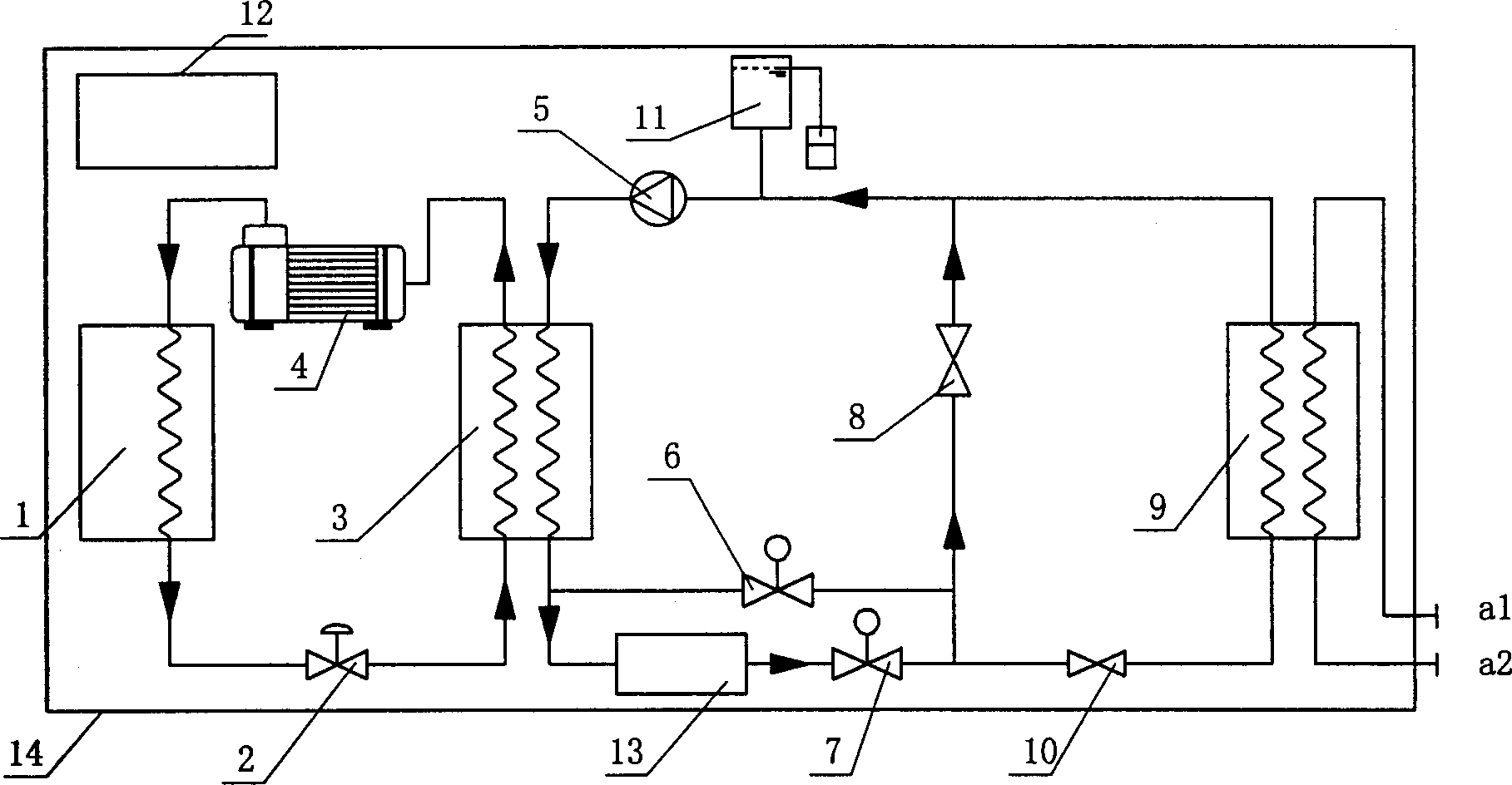
[0041] (d) When the ice storage system operates in the combined cooling mode of the chiller and the ice tank (such as Figure 5As shown), the refrigerant cycle runs in the air-conditioning condition, and the refrigerant flows along the direction of the compressor 4, the condenser 1, the throttling device 2, and the evaporator 3, and returns to the compressor 4. The brine pump 5 in the brine circuit is running, the solenoid valve 8 is closed, the solenoid valve 10 is opened, and the electric control valves 6 and 7 are opened to a certain opening degree to control the temperature of the brine entering the heat exchanger 9; After being pressurized by the brine pump 5, the refrigerant flows into the evaporator 3 to absorb the cooling capacity, and then flows into the ice storage tank 13 to melt the ice and get cold, then passes through the electric regulating valve 7 and the secondary refrigerant passing through the electric regulating valve 6 After the agent is mixed, it enters t...
Embodiment 3
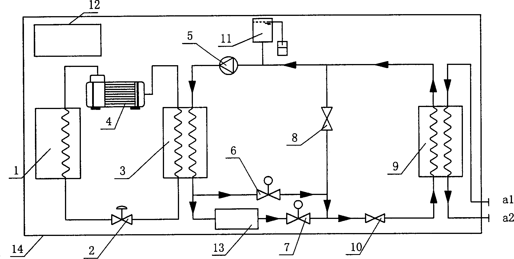
[0044] In various operating modes, the flow direction of the brine is the same as that in Embodiment 1. Embodiment 3: Integrated ice storage unit in the form of parallel single heat exchanger:
[0045] Figure 7 It is the connection diagram of the integrated ice storage unit in the form of parallel single heat exchanger of the present invention.
[0046] and figure 1 The integrated ice storage unit in the form of a single pump in series and Image 6 In order to solve the unnecessary resistance loss in the evaporator under the independent cooling mode of the ice tank, and to increase the inlet temperature of the ice tank under the joint cooling mode of the ice tank cooler , improve the cooling rate of the ice tank, and change the original serial structure of the ice tank and the heat exchanger into a parallel structure.
[0047] (a) When the ice storage system operates in the ice storage mode (such as Figure 8 As shown), the refrigerant cycle runs in the ice storage condi...
PUM
 Abstract
Description
Claims
Application Information
 - R&D
- Intellectual Property
- Life Sciences
- Materials
- Tech Scout
- Unparalleled Data Quality
- Higher Quality Content
- 60% Fewer Hallucinations
Browse by: Latest US Patents, China's latest patents, Technical Efficacy Thesaurus, Application Domain, Technology Topic, Popular Technical Reports.
© 2025 PatSnap. All rights reserved.Legal|Privacy policy|Modern Slavery Act Transparency Statement|Sitemap|About US| Contact US: help@patsnap.com