Timing synchronizaation and phase/frequency correction of QPSK signals

A technology of frequency and frequency offset, applied in the field of digital demodulation of quadrature phase shift keying signal

Inactive Publication Date: 2002-12-11
TECH INC
View PDF0 Cites 5 Cited by
  • Summary
  • Abstract
  • Description
  • Claims
  • Application Information

AI Technical Summary

Problems solved by technology

The data subframe is then resampled using the resampling timing estimate

Method used


Image

  • Timing synchronizaation and phase/frequency correction of QPSK signals
  • Timing synchronizaation and phase/frequency correction of QPSK signals
  • Timing synchronizaation and phase/frequency correction of QPSK signals

Examples


Embodiment Construction

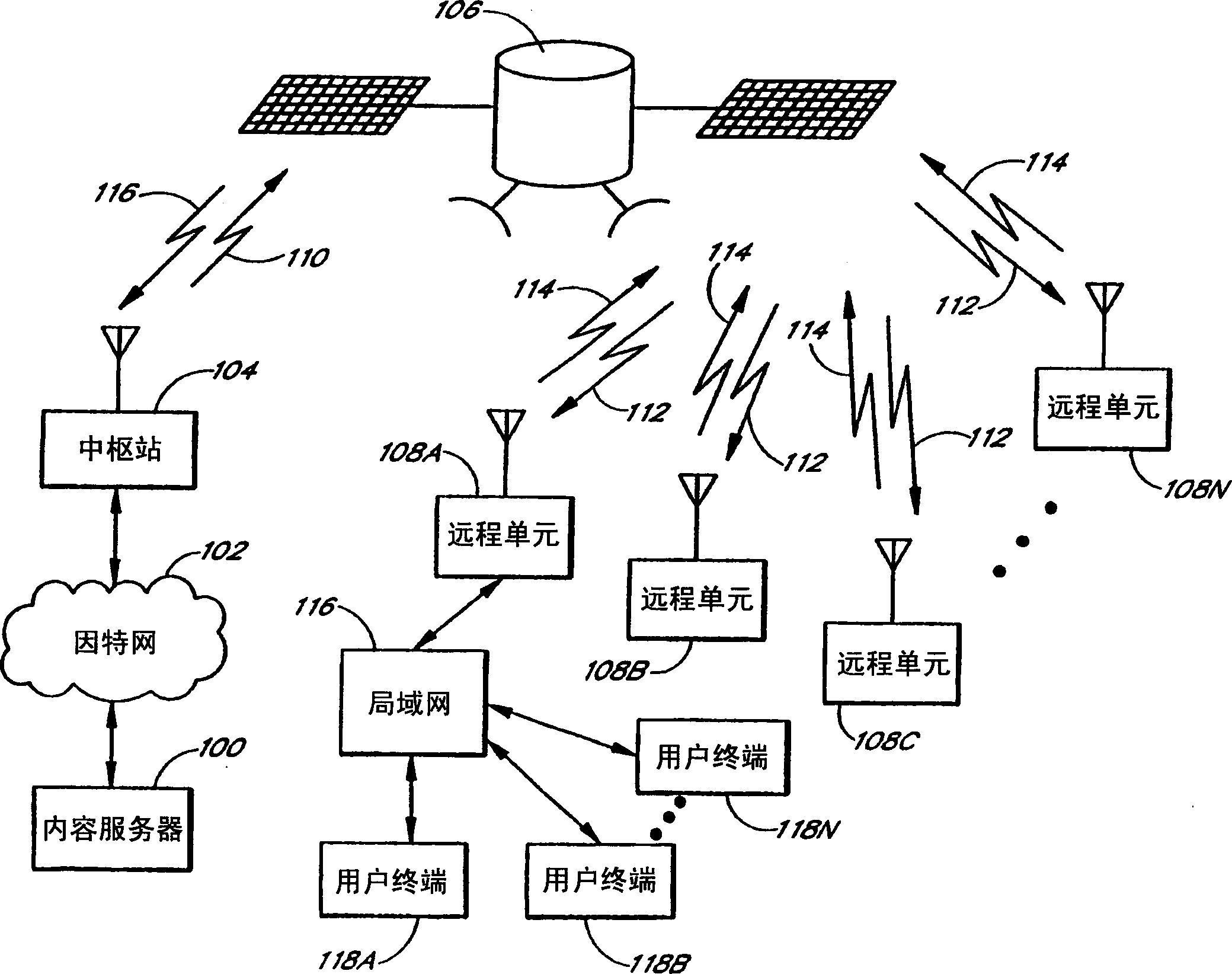
[0017] figure 1 is a block diagram illustrating an example system implementing the invention. figure 1 The system in provides high-speed, reliable Internet communication services through satellite links.

[0018] especially in figure 1 100, the content server 100 is coupled to the Internet 102, which in turn is coupled to a hub station (hub station) 104 to enable the hub station 104 to request and receive digital data from the content server 100. The hub station 104 also communicates via satellite 106 with a plurality of remote units 108A- 108N. For example, hub station 104 transmits signals to satellites 106 via forward uplink 110 . Satellite 106 receives signals from forward uplink 110 and retransmits these signals through forward downlink 112 . Forward uplink 110 and forward downlink 112 are collectively referred to as the forward link. Remote units 108A-108N monitor one or more channels, including forward links, to receive designated remote units and broadcast message...


PUM


Abstract

A method and apparatus for digitally demodulating a QPSK signal includes resampling a first portion of a digitally sampled data subframe using a plurality of predetermined timing hypotheses. The timing offset is determined from analysis of the resampled data. The digitally sampled data subframes are then resampled based on the timing estimates. The modulation of the resampled data subframe is then removed by squaring the complex I/Q pair twice. A chirp-Z transform is performed on the data from which the modulation has been removed to shift the data into the frequency domain. Use the highest spectral power to determine the frequency offset. A phase offset is determined and the resampled data bursts are derotated and phase-shifted based on the phase offset and the frequency offset.

Description

technical field [0001] The present invention relates to wireless communication systems, and in particular, the present invention relates to digital demodulation of quadrature phase shift keying (QPSK) signals. Background technique [0002] The digital demodulation of QPSK signal can be realized by adopting the tracking loop scheme. The tracking loop generates resampling timing and is also used to remove frequency and phase offsets, also known as residual frequency and phase, from incoming data symbols. Typically, the system operates on a new sample pair at a time. The system employs a feedback loop to track and correct timing, frequency and phase offsets in the incoming data stream. [0003] These feedback loops require carefully set tracking loop gains. Plus, they require capture cycles that the feedback loop has time to lock into. This known system requires the use of a relatively long header at the beginning of each new data transmission in order to provide feedback l...

Claims


Application Information

Patent Timeline
Patent Type & Authority Applications(China)
IPC IPC(8): G06F11/00G06F11/14H03J7/06H04B7/165H04B7/185H04L7/00H04L7/04H04L12/56H04L27/22H04L27/227H04L29/06H04N21/235H04N21/236H04N21/2385H04N21/434H04N21/435H04N21/438H04N21/61H04N21/643
CPCG06F11/0757G06F11/1441H03J7/065H04B7/18582H04L7/0029H04L7/04H04L27/22H04L27/2276H04N21/235H04N21/23614H04N21/2385H04N21/4348H04N21/435H04N21/4381H04N21/6143H04N21/64322H04W80/06H04L69/16H04L69/166H04L69/161H04L69/163H04L69/168H04L27/227H04L69/08H04L9/40
Inventor 唐纳德·W·贝克尔威廉·E·L·利
Owner TECH INC
Why Eureka
Try Eureka