Plasma discharge reactor having multiple rotary disk electrodes with more tips

A technology of rotating electrode and plasma, applied in the field of plasma discharge reactor, can solve problems such as difficulty in realizing industrialization, and achieve the effect of less carbon deposition and high yield

Inactive Publication Date: 2003-01-15
TIANJIN UNIV
View PDF0 Cites 17 Cited by
  • Summary
  • Abstract
  • Description
  • Claims
  • Application Information

AI Technical Summary

Problems solved by technology

They are difficul

Method used


Image

  • Plasma discharge reactor having multiple rotary disk electrodes with more tips
  • Plasma discharge reactor having multiple rotary disk electrodes with more tips

Examples


Embodiment Construction

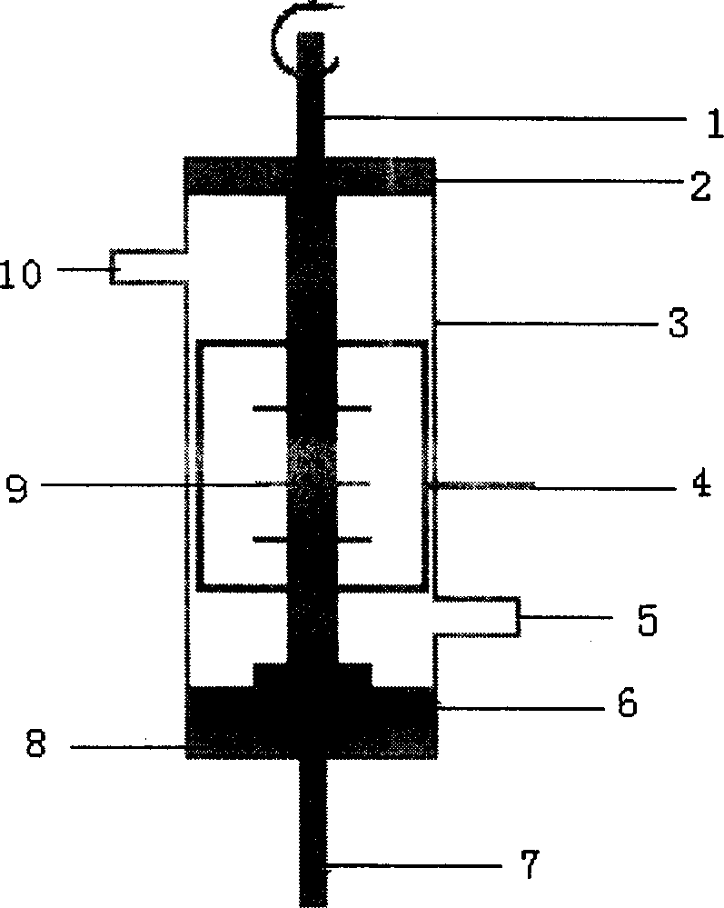
[0011] The present invention is described as follows in conjunction with the accompanying drawings: In the figure, the inner diameter of the insulating shell of the reactor is 11-1010 mm. The distance between multiple concentric discs on the rotating electrode column in the casing is more than 10mm, the diameter of the column is 3-50mm, the diameter of the disc is 5-10mm, and the thickness is 1-5mm. The height is 1-20mm, and the number of teeth is more than 4. The experimental process mainly includes five parts: gas flow control, electrode rotation control, high voltage power supply, digital oscilloscope and gas chromatographic analysis. Reactive gas CH 4 and H 2 The flow of the gas passes through the mass flow controller in two paths and is displayed by the flow display instrument. After mixing, it enters the gas chromatograph and the reactor successively. During the reaction, the reaction gas passes through the discharge zone almost continuously. The high-voltage power s...


PUM


Abstract

A plasma discharging reactor with rotating electrode is composed of cylindrical casing, fixed cylindrical electrode in the casing, and rotating electrode. Said rotating electrode has multiple multi-tip concentric disks fixed to it, the top end extended out of the casing and driven by drive mechanism, and the lower end in the recess of metallic base connected to high-voltage power supply. Its advantages are high conversion rate of methane (55-75%), high output rate of C2 hydrocarbon (45-70%) and high selectivity of C2 hydrocarbon (more than 95%).

Description

technical field [0001] The invention relates to a plasma discharge reactor with multi-point and multiple disk rotating electrodes. An innovative technology belonging to the plasma discharge reactor, Background technique [0002] With the increasing shortage of oil resources, people pay more and more attention to the development and utilization of the world's large reserves of energy natural gas. Methane (CH 4 ) is the main component of natural gas. Due to CH 4 Molecules have high stability, with CH 4 Direct coupling system C 2 Hydrocarbons (ethane, ethylene, acetylene) are very unfavorable thermodynamically, and no breakthrough has been made in the direct coupling of conventional catalytic means, while the plasma discharge reaction is for CH 4 Coupling is a very effective method, which has become a research hotspot in the interdisciplinary frontier of physical chemistry in recent years. The plasma discharge reactor is the CH in the plasma stat...

Claims


Application Information

Patent Timeline
IPC IPC(8): B01J19/08C07C2/80
Inventor 徐根慧崔锦华
Owner TIANJIN UNIV
Why Eureka
Try Eureka