Finger print input device

A fingerprint input and fingerprint technology, applied in image data processing, sensors, diagnosis, etc., can solve the problem that the protection function of two-dimensional image sensor is not always enough

Inactive Publication Date: 2003-01-22
NEC PERSONAL COMPUTERS LTD
View PDF1 Cites 26 Cited by
  • Summary
  • Abstract
  • Description
  • Claims
  • Application Information

AI Technical Summary

Problems solved by technology

In addition, depending on the thickness of the panel, the fingerprint image does not always have enough contrast, and its protection function for the 2D image sensor is not always sufficient

Method used


Image

  • Finger print input device
  • Finger print input device
  • Finger print input device

Examples


Embodiment 2

[0204] Next, Embodiment 2 will be described. Figure 16 and 17 is a partial cross-sectional view of two types of fingerprint input devices according to Embodiment 2. The cover film 8 of the two-dimensional image sensor is used to stabilize the characteristics of the sensor unit, it should be formed during the semiconductor manufacturing process, and is generally thinner than several micrometers due to the semiconductor manufacturing method used. If a finger repeatedly presses directly on the cover film 8, the durability of the cover film 8 is adversely affected by the contact of the finger. Therefore, in Example 1, a transparent solid film 4 is provided, and the thickness, refractive index, and hardness of the transparent solid film 4 are determined. Among these parameters, it is the thickness condition that contradicts the durability condition, that is, the thinner the transparent solid film 4, the clearer the obtained image. The thicker the transparent solid film 4, the b...

Embodiment 3

[0217]In Embodiment 3, a microlens layer which has been used in recent years to improve the sensitivity of a fingerprint image sensor is used as a protective film.

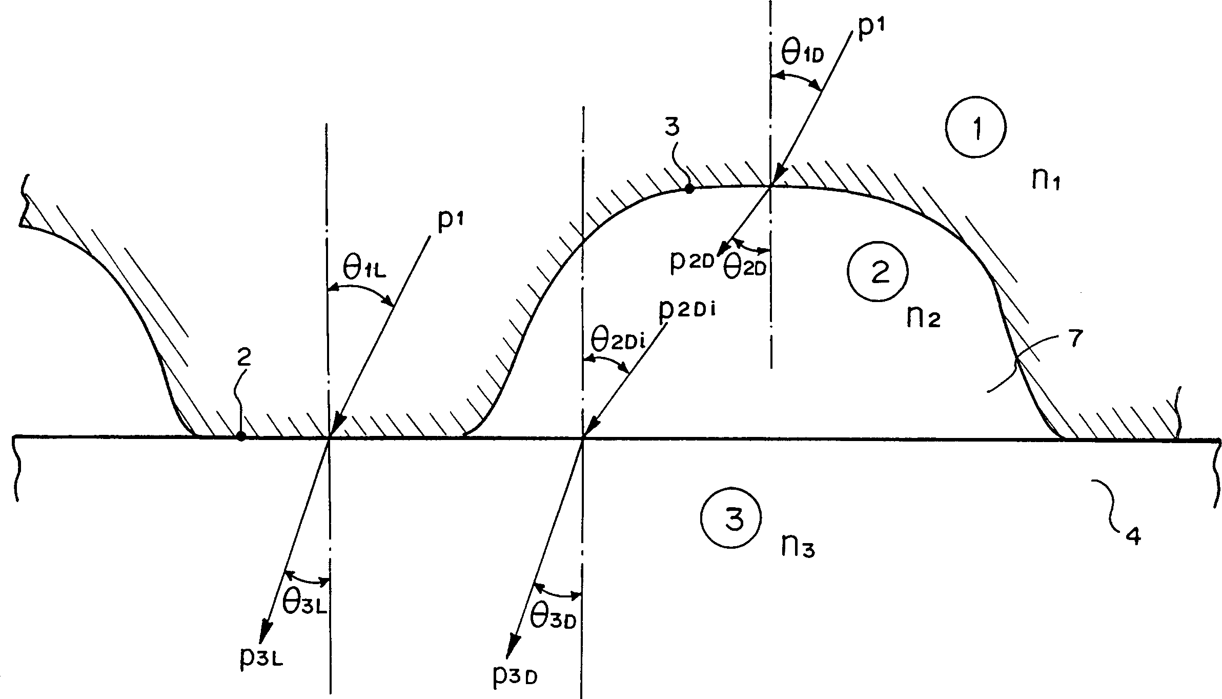
[0218] In Embodiment 3, the microlens 3 is a dome-shaped transparent solid, which is covered directly above the photosensitive part of the image sensor, as shown in FIG. 20 . As a result, light incident on parts other than the photosensitive part is condensed on the photosensitive part, thereby improving the light detection sensitivity of the sensor. When the fingerprint ridge portion is in contact with the microlens 13, the shape of the ridge is indicated by 13-1, and the photodetection sensitivity of the sensor is improved by converging light on the photosensitive portion. However, the light incident on the microlens 13 from the valley portion 13-2 is emitted to a space, and the light from this portion becomes unusable. As a result, light within 100% of the ridge portion of the fingerprint cannot be detected. ...

Embodiment 4

[0226] In Embodiment 4, the fluctuation of the transmitted light due to the pulsating flow of blood is utilized, and during the measurement, it is used to identify whether the fingerprint is a living body's fingerprint based on this pulsating characteristic to prevent illegal finger replicas use. Figure 26 The block diagram of shows the pulse detection circuit in Embodiment 4. The operation of the pulsation detection circuit is as follows. An infrared ray having a wavelength of 800 to 950 nm was used as measurement light, and a spectral filter having a transmission wavelength equal to that of the above-mentioned infrared ray was also used. In this wavelength band, blood containing a large amount of oxygen (artery) and blood containing a small amount of oxygen (vein) have little difference in absorption coefficient from each other, and the fluctuation of the amount of transmitted light is about 10%. According to the change in the light absorption amount of the blood, the pea...


PUM


Abstract

The present invention provides a fingerprint input device capable of obtaining a fingerprint image presenting sufficient contrast. The fingerprint input device includes: a two-dimensional image sensor for picking up a fingerprint image from a fingerprint measured portion of a measurement target finger; and a transparent solid film mounted on an image pickup surface of the two-dimensional image sensor, the fingerprint measured portion being mounted on the transparent solid film when the two-dimensional image sensor picks up the fingerprint image, wherein the fingerprint input device picks up an image of a fingerprint ridgeline portion in the fingerprint measured portion as a light portion, and picks up an image of a fingerprint valley portion in the fingerprint measured portion as a dark portion through an air layer, and a refractive index of the transparent solid film satisfies that contrast of the image is more than a given value.

Description

technical field [0001] The invention relates to a fingerprint input device, in particular to a fingerprint input device which uses a two-dimensional image sensor to directly acquire a fingerprint image. Background technique [0002] Conventionally, this type of fingerprint input device usually uses optical elements such as lenses, prisms and optical fibers to irradiate light on the fingerprint of the fingertip at a predetermined angle, gathers the reflected light of the fingerprint and outputs a fingerprint image. In addition, a system has been developed in which a fingerprint image is directly inputted using an electrostatic capacity instead of acquiring a fingerprint image using an optical system. [0003] Research has been conducted on a system that uses optical devices to directly input fingerprint images. Known in such systems are a light reflection system for directing light onto the skin of the fingertip and using it to reflect light, and a light transmission system ...

Claims


Application Information

Patent Timeline
Patent Type & Authority Applications(China)
IPC IPC(8): A61B5/117G06K9/00G06T1/00H01L27/14
CPCG06K9/00046A61B5/1172G06V40/1324G06F18/00
Inventor 樋口辉幸
Owner NEC PERSONAL COMPUTERS LTD
Why Eureka
Try Eureka