

Rare-earth element doped glass double-clad optic fibre and mfg. method thereof
A rare earth element and double-clad technology is applied in the field of rare earth element-doped glass double-clad optical fiber and its preparation. The effect of large gain and simple preparation and drawing process
- Summary
- Abstract
- Description
- Claims
- Application Information
AI Technical Summary
Problems solved by technology
Method used
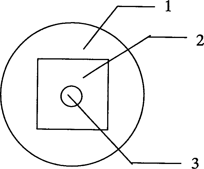
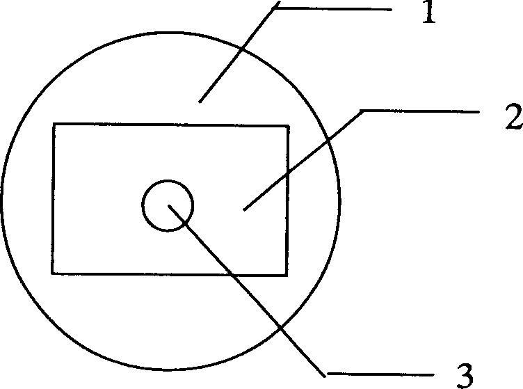
Image

Examples
specific Embodiment 1
[0034] Specific Example 1-Group 1 Materials
[0035] Group 1
Group 2
Group 3
Composition (mol%)
Fiber core
Inner cladding
Fiber core
Inner cladding
Fiber core
Inner cladding
P 2 O 5
60.0
61.0
55.0
54.5
70
71
Al 2 O 3
4.0
4
5.0
5.0
7
8
BaO
10.0
10.0
14.0
16.5
4
4
Na 2 O
4.0
4.5
3.0
3.0
8
8
K 2 O
15.0
15.5
13.0
13.0
5.6
5
Nb 2 O 5
0.4
0.4
2
2
0.5
0.5
La 2 O 3
0.3
0.3
1.5
1.5
0.3
2.8
Y 2 O 3
0.2
5.3
4.5
4.4
0.5
0.5
Group 1
Group 2
Group 3
Composition (mol%)
Fiber core
Inner cladding ...
specific Embodiment 2
[0041] Specific Example 2-Group 2 and 3 Materials
[0042] The glass formulations of the second and third groups are shown in Table 3. The melting process of the core material and the inner cladding glass is the same as that of Example 1.
[0043] For the second group, the core rod glass is processed into a diameter of 3mm (d 芯棒 =500d 芯 ), the preform with a length of 60mm, the inner cladding preform is processed into a processing size of 50mm×50mm×80mm (d 包棒 =(400×400)d 包 ), drill an inner hole with a diameter of 2mm and an inner cladding rod with a depth of 60mm at the center of the upper and lower end faces. The subsequent steps and wire drawing process are the same as in Example 1. The final numerical aperture of the double-clad fiber composed of the second core material and inner cladding material is 0.08, the core diameter is 6 μm, the inner cladding side length is 125 μm, and the outer diameter is φ170 μm. For the third group, the core rod glass is processed into a diameter...
specific Embodiment 3
[0044] Specific Example 3-4th, 5th and 6th group materials
[0045] The fourth, fifth, and sixth groups in Table 4 are all phosphate glass systems as the core material, and silicate glass systems as the inner cladding.
[0046]For the fourth, fifth, and sixth groups, the melting of the core glass is the same as in the specific embodiment 1. The melting of the inner cladding glass is a raw material synthesized according to the inner cladding formula selected by the above-mentioned silicate glass system Take 3000 grams and mix it evenly and melt it directly in a 2.0 liter platinum crucible at a melting temperature of 1350°C. Stirring and clarification are carried out in sequence. The whole process takes more than 5 hours. Finally, it is cast on an iron mold with a size of 120mm×70mm×50mm, and then moved into a muffle furnace preheated to a material transition temperature Tg of 460℃ for annealing. It is held for 2 hours and then cooled to 380℃ at a rate of 2℃ / hr. Then lower to room t...
PUM
| Property | Measurement | Unit |
|---|---|---|
| Diameter | aaaaa | aaaaa |
| Diameter | aaaaa | aaaaa |
Abstract
Description
Claims
Application Information