


Quick Research
Generate reliable direction feasibility study reports for your R&D in just a few steps.

Technical Q&A
Discover and master advanced knowledge NOW. Basics, ideas, possibilities, all at once.

Find Solutions
As an expert in R&D theories, this can generate solutions to your technical problems instantly.

Evaluate Feasibility
Analyze your overall solution with one click, know your potential R&D risks in advance.

Monitor Landscape
Get weekly tech updates, stay abreast of the latest tech innovations and key insights.
Electrochemical element and electrochemical element device
一种电化学元件、电极的技术,应用在电化学元件领域,能够解决难以提高输出电压、输出电压低到几毫伏等问题
- Summary
- Abstract
- Description
- Claims
- Application Information
AI Technical Summary
Problems solved by technology
Method used
Image

Examples
Embodiment approach 1
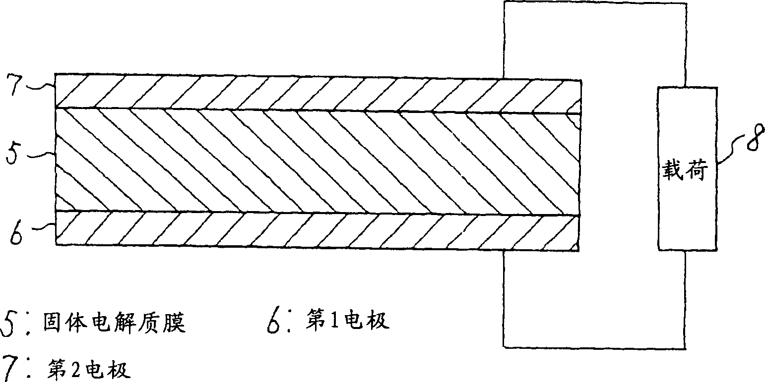
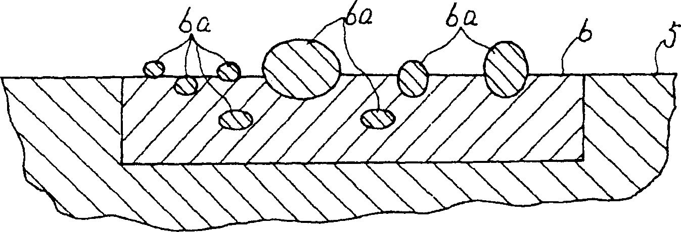
[0020] figure 1 Shown is a configuration diagram of the first embodiment. figure 1 Among them, 5 is a solid electrolyte membrane, which is a solid electrolyte with hydrogen ion conductivity. The solid electrolyte membrane 5 is, for example, Nafion-117 (registered trademark) manufactured by Dupont Corporation. 6 is a first electrode with a catalytic function and hydrophilicity formed on one side of the solid electrolyte membrane 5, which is formed by alloying two metal components with different oxidation tendencies, oxidizing the metal component with a high oxidation tendency and It is formed by dispersing oxide fine particles 6a on the surface and pressing them to the solid electrolyte membrane 5 . In the formation of the first electrode 6, for example, an alloy formed by solid solution of Ti with 20 (atom)% in Pt with catalytic function and power supply function is subjected to heat treatment at 500°C in pure oxygen at 900 atmospheric pressure, such as figure 2 Only Ti ...
Embodiment approach 2
[0034] Figure 5 Shown is a configuration diagram of Embodiment 2. Figure 5 In , the portion indicated by 5 is the same as that in Embodiment 1. 9 is a first electrode formed on one side of the solid electrolyte membrane 5, which consists of a reaction part 9a with a catalytic function on the adjacent side of the solid electrolyte membrane 5 and a hydrophilic part 9b on the surface of the reaction part 9a. constitute. Furthermore, the hydrophilic portion 9b is formed by capillarity by enlarging the ratio of the depth direction to the pore diameter of a porous metal obtained by plating platinum on the surface of titanium, for example. 10 is the second electrode formed on the other side of the solid electrolyte membrane 5, which is composed of a catalytic reaction part 10a on the adjacent side of the solid electrolyte membrane 5 and a hydrophobic hydrophobic part 10b on the surface of the reaction part 10a. . Moreover, the hydrophobic portion 10b is, for example, made of CF...
Embodiment approach 3
[0040] Image 6 Shown is a configuration diagram of the third embodiment. Image 6 In , the portion indicated by 5 is the same as that in Embodiment 1. 12 is the first electrode with catalytic function formed on one side of the solid electrolyte membrane 5 by the Pt electroless plating method, and its surface is endowed with hydrophilicity by irradiation of at least one of plasma, vacuum ultraviolet light and ozone. Also, the first electrode 12 may be imparted with hydrophilicity by depositing and adhering a substance having a hydrophilic group. 13 is the second electrode with catalytic function formed by Pt electroless plating method on the other side of solid electrolyte membrane 5, which is made of any one of organic compound and organic fluorine compound as raw material by CVD method, sputtering method, evaporation method, etc. It is formed by depositing and adhering hydrophobic components on the surface by either plating method or dipping method. For example, hydrophob...
PUM
 Abstract
Description
Claims
Application Information
 - R&D Engineer
- R&D Manager
- IP Professional
- Industry Leading Data Capabilities
- Powerful AI technology
- Patent DNA Extraction
Browse by: Latest US Patents, China's latest patents, Technical Efficacy Thesaurus, Application Domain, Technology Topic, Popular Technical Reports.
© 2024 PatSnap. All rights reserved.Legal|Privacy policy|Modern Slavery Act Transparency Statement|Sitemap|About US| Contact US: help@patsnap.com