

Chargeable magnesium battery
A magnesium battery and battery technology, applied in battery electrodes, secondary batteries, circuits, etc., can solve instability and other problems, and achieve the effects of good safety, low price, large development and application prospects
- Summary
- Abstract
- Description
- Claims
- Application Information
AI Technical Summary
Problems solved by technology
Method used
Image

Examples
Embodiment 1
[0024] Production of Negative Electrode
[0025] MgH 2 Mix with metal elements Ni, Ti, etc. in a molar ratio of 1:0.01:0.01, ball mill for 6 hours under argon atmosphere, keep warm for 4 hours at 560°C under argon atmosphere, cool, and then ball mill in a high-speed ball mill for 80 hours, powder The size is 50-600nm, the magnesium alloy powder is soaked in 0.01M magnesium fluoride for 1 minute, the magnesium alloy powder, carbonyl nickel powder and PTFE are mixed into a paste, coated on the copper mesh, and pressed under 30MPa pressure to make a diameter of 13mm , and a negative electrode sheet with a thickness of 1 mm was stored in a vacuum desiccator.
[0026] Positive electrode production
[0027] Weigh an appropriate amount of CoCl 2 ·6H 2 O and MgCl 2 ·6H 2 O, the molar ratio of the two is 2:1, prepare a mixed solution with a certain concentration, adjust the pH to 6~7 with ammonia water, and then add it to an appropriate amount of oxalic acid solution, a large amo...
Embodiment 2
[0031] Negative pole piece is made identical with embodiment 1
[0032] Production of the positive pole piece
[0033] Under hydrogen atmosphere, (NH 4 ) 2 MoS 4 Heating at 850°C for 6 hours, cooling, and ball milling in high-speed ball milling for 80 hours, the powder particles are in the range of 50-800nm, and the MoS 2 Powder, acetylene black powder, and PTFE (85:10:5) were mixed into a paste, coated on an aluminum mesh, pressed into a positive electrode sample with a diameter of 13 mm and a thickness of 1 mm under a pressure of 30 MPa, and stored in a vacuum desiccator. Assembly of simulated battery
[0034] In addition to using MoS 2 Positive pole piece replaces MgCo 2 o 4 Except for the positive pole piece, others are exactly the same as in Example 1.
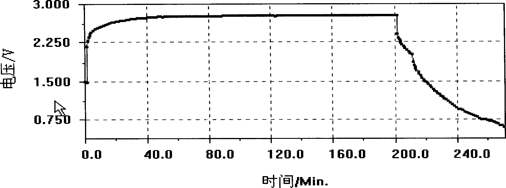
[0035] The opening voltage of the simulated battery is 1.4V, 0.1C charge and discharge, and the charging voltage is stable at 2.8V. The simulated battery can be reversibly charged and discharged, and the discharge...
Embodiment 3
[0037] Mix Mg powder, metal copper powder and nickel powder in a molar ratio of 1:0.01:0.005, ball mill for 6 hours in an argon atmosphere, heat at 560°C for 4 hours in an argon atmosphere, cool, and ball in a high-speed ball mill for 80 hours , the powder size is in the range of 80-800nm, the magnesium powder is soaked in 0.01M magnesium fluoride for 3 minutes, the magnesium alloy powder, carbonyl nickel powder and PTFE (85:10:5) are adjusted into a paste, and coated on the copper On the net, under a pressure of 30MPa, press it into an electrode sheet with a diameter of 13mm and a thickness of 1m, and store it in a vacuum desiccator. The production of the positive electrode sheet is the same as in Example 1. The fabrication of the simulated battery is the same as in Example 1.
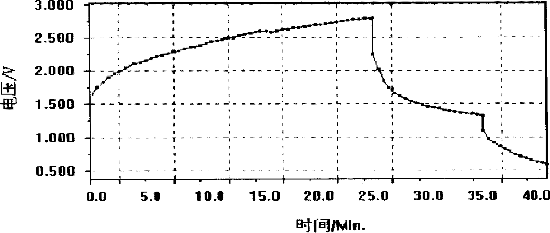
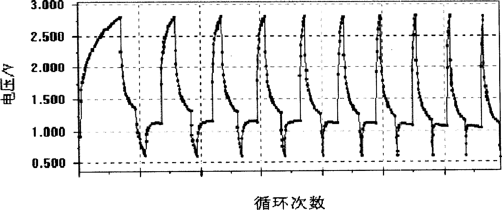
[0038] The opening voltage of the simulated battery is 2.0 volts, and it is charged and discharged at 0.1C. The average charging voltage is about 2.85 volts, and the discharging voltage is 1.75 V. Th...
PUM
| Property | Measurement | Unit |
|---|---|---|
| particle size | aaaaa | aaaaa |
| size | aaaaa | aaaaa |
Abstract
Description
Claims
Application Information