Double-ring coupled all optical buffer storage

A technology of optical buffer and coupler, which is applied in the coupling of optical waveguide, electromagnetic wave transmission system, electrical components, etc., can solve the problems of short storage time, poor symmetry and stability, and complex structure, and achieve simple structure and symmetry Good, long storage time effect

Inactive Publication Date: 2003-05-14
BEIJING JIAOTONG UNIV
View PDF0 Cites 31 Cited by
  • Summary
  • Abstract
  • Description
  • Claims
  • Application Information

AI Technical Summary

Problems solved by technology

But all the schemes are based on the single-fiber ring structure of 2×2 coupler, not only the structure is complicated, but also the symmetry and stability are poor, and the storage time is relatively short

Method used


Image

  • Double-ring coupled all optical buffer storage
  • Double-ring coupled all optical buffer storage
  • Double-ring coupled all optical buffer storage

Examples


Embodiment 1

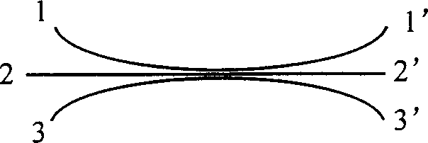
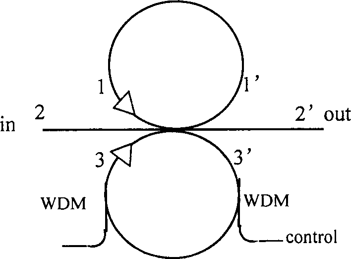
[0022] figure 2 in, cf figure 1 , it can be seen that the double-ring coupling all-optical buffer of the present invention is to connect and close the two side arms of the 3×3 coupler with optical fiber material to form two equal-length optical fiber rings, and the middle arm is used as the input of the all-optical buffer , output port. Two WDMs are connected to one of the optical fiber rings to import and export control light. The 3×3 coupler used here is made to conform to the following matrix during the fabrication process: E 1 E 2 E 3 ( z ) = 1 / ...

Embodiment 2

[0026] Such as figure 2 As shown, based on the different control modes of the control light for maintenance and readout, the double-ring coupling all-optical buffer of the present invention can also adopt another scheme: other methods can be used to make the upper and lower optical fiber rings (11' and 33' ) have different lengths, so that when the optical signal passes through it, a fixed phase difference -π radians (or its integer multiples) will be generated, so that the signal can be stored in the ring all the time, and it is no longer necessary to control the light. When it is to be read out, the control light is used to make one of the rings produce a π radian phase difference, so as to read out. This approach is useful for long-latency RAM.

[0027] In embodiment 1 and embodiment 2, what the storage of photon adopts is the optical fiber loop, along with the further development of optical waveguide technology and manufacturing technology, this optical fiber loop also c...

Embodiment 3

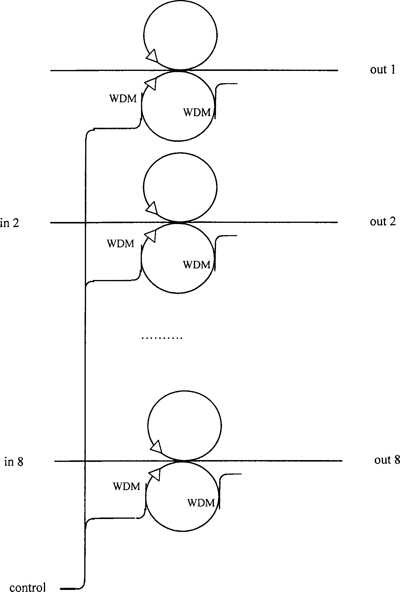
[0029] On the basis of embodiment 1 or embodiment 2, a plurality of such all-optical buffers (such as 8 such buffers) can be utilized to form an all-optical buffer of parallel signals under the control of the same read-write control optical signal device. For example image 3 As shown, an all-optical buffer for a parallel signal with 8 bits as a parallel byte.


PUM


Abstract

The double-ring coupled all optical buffer storage based on 3x3 fiber coupler stores light signal has its read / write operation under control of one other light signal. Two side ports of the 3x3 fibercoupler constitute the double-ring structure via fiber feedback and the middle ports are used as the input and output of the buffer storage. Control light is led in and led out one fiber ring via twoWDM fiber coupler, and the phase difference between the two ring light signals is altered by means of cross phase modulation effect to realize the write-in and real-out of light signal in fiber ring.The control light signal may be positive logic one or negative logic one. If necessary, light amplifier may be added into the fiber ring for power compensation. Several buffer storages can be constituted into one parallel signal light buffer storage.

Description

1. Technical field [0001] The invention relates to an all-optical buffer implemented based on a 3*3 fiber coupler. The all-optical buffer not only caches optical signals, but also controls the read and write operations by optical signals instead of electrical signals, and can be read randomly as needed. It is the basic component of optical information processing and will be widely used in optical fiber communication, optical signal (information) processing, optical packet switching, optical computing and other fields. It is mainly used to temporarily store high-speed optical signals. 2. Background technology [0002] Just as the electrical buffer temporarily stores the electrical signal in the chip for a period of time, and then reads it out under the control of the electrical control signal as needed, the optical buffer buffers the optical signal in a special device and can control the signal. A device for writing and reading under control. International research on all-...

Claims


Application Information

Patent Timeline
Patent Type & Authority Applications(China)
IPC IPC(8): G02B6/26H04B10/2557
Inventor 吴重庆付松年董晖
Owner BEIJING JIAOTONG UNIV
Why Eureka
Try Eureka