

Mfg. method of metal ripple tubes
A technology of metal bellows and manufacturing methods, which can be applied to other home appliances, household appliances, applications, etc., can solve the problems of poor surface treatment, poor consistency of bellows, low production efficiency, etc., and achieve rapid melting and solidification. Narrow influence zone and improved efficiency
- Summary
- Abstract
- Description
- Claims
- Application Information
AI Technical Summary
Problems solved by technology
Method used
Image

Examples
Embodiment 1
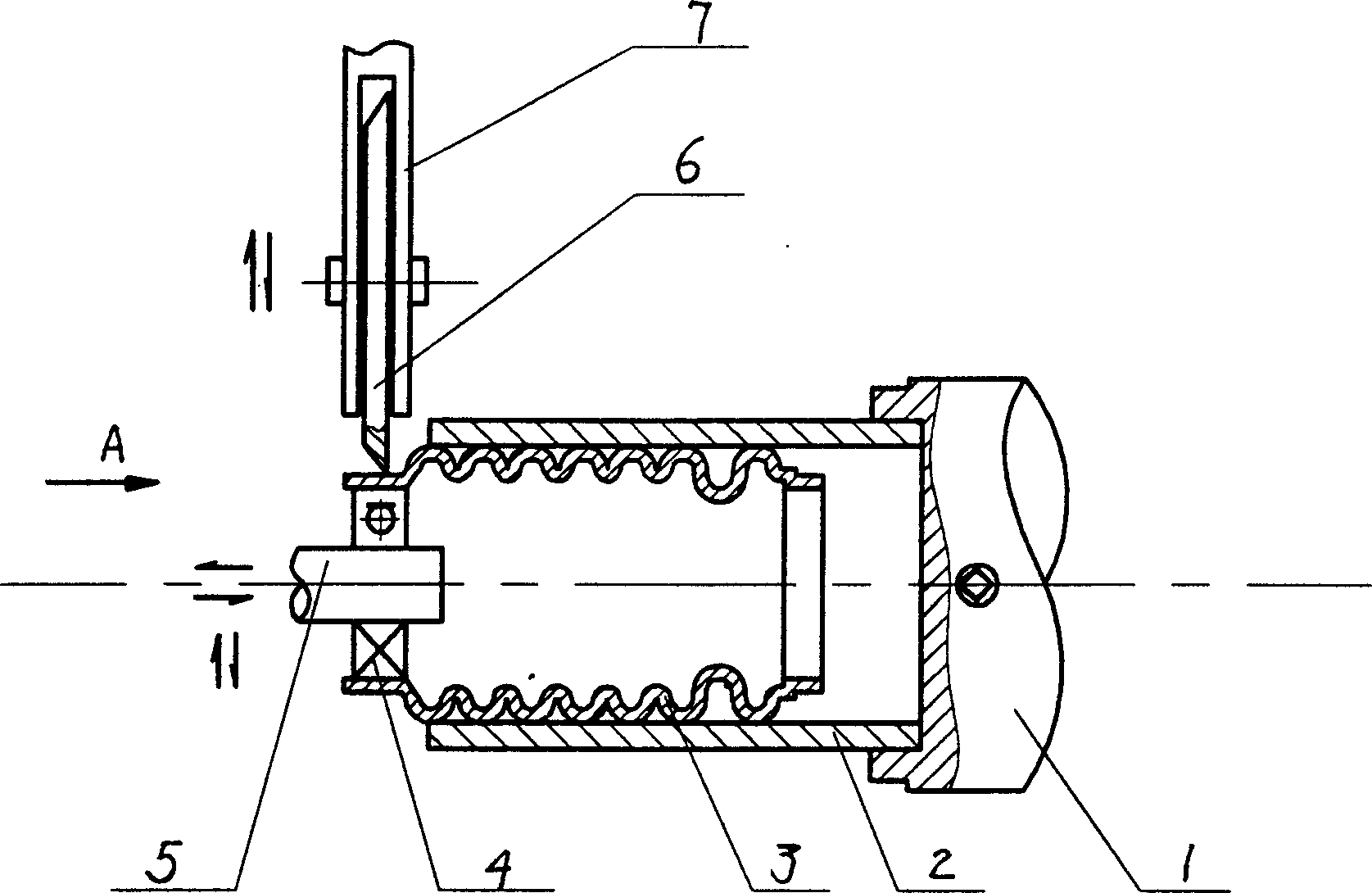
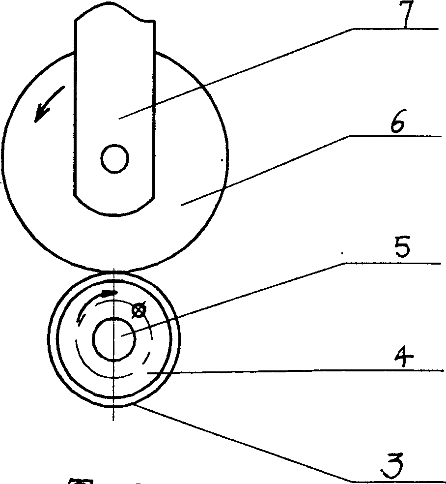
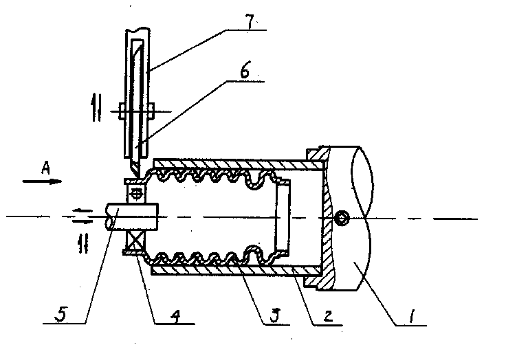
[0016] Take the bright annealed cold-rolled stainless steel strip with a thickness of 0.1-0.2mm, roll it into a tube, and use an argon arc welding machine or a micro-beam plasma welding machine with strong and concentrated arc energy and no arc drift at a small current. The butt joints of the stainless steel strips are welded, and the rolled cold-rolled stainless steel strips are welded into extremely thin-walled steel pipes; they are cut off and then shaped by a bellows forming machine; figure 1 , figure 2 As shown, after forming, the bellows 3 is clamped on the operating table with a clamp consisting of a chuck 1 and a process jaw 2, and a tool holder 5 is used to push the rigid support (bearing) 4 into the metal bellows 3 At the edge trimming place, install the hob 6 on another tool rest 7, align the hob 6 with the edge trimming of the metal bellows, and perform edge trimming. After edge trimming, the rigid support 4 is withdrawn from the metal bellows 3; The back metal b...
Embodiment 2
[0018] Take the bright annealed cold-rolled stainless steel strip with a thickness of 0.1-0.2mm, roll it into a tube, and use an argon arc welding machine or a micro-beam plasma welding machine with strong and concentrated arc energy and no arc drift at a small current. The butt joints of the stainless steel strips are welded, and the rolled cold-rolled stainless steel strips are welded into extremely thin-walled steel pipes; cut off, and then formed by a bellows forming machine; steel wheels with elastic mandrels made of nylon or hard rubber are used The correcting machine, the corrugated pipe after forming is set on the elastic mandrel steel wheel for correcting; such as figure 1 , figure 2 As shown, the corrected corrugated pipe 3 is clamped on the operating table with a clamp consisting of a chuck 1 and a process jaw 2, and a tool holder 5 is used to push the rigid support (bearing) 4 into the metal bellows 3 At the edge trimming place, install the hob 6 on another knife...
Embodiment 3
[0020] Take the bright annealed cold-rolled stainless steel strip with a thickness of 0.1-0.2mm, roll it into a tubular shape, and use an argon arc welding machine or a micro-beam plasma welding machine with strong and concentrated arc energy and no arc drift at a small current to weld the cold-rolled stainless steel strip. The butt joints of the strips are welded, and the rolled cold-rolled stainless steel strips are welded into extremely thin-walled steel pipes; they are cut off and then formed by a bellows forming machine; figure 1 , figure 2 As shown, the molded corrugated pipe 3 is clamped on the operating table with a fixture consisting of a chuck 1 and a process jaw 2, and a tool holder 5 is used to push the rigid support (bearing) 4 into the metal bellows 3 At the edge trimming place, install the hob 6 on another knife rest 7, align the hob 6 with the edge trimming of the metal bellows, and perform edge trimming. After edge trimming, the rigid support 4 is withdrawn f...
PUM
 Abstract
Description
Claims
Application Information