Aperture real image transfer unit

A technology of transmitting device and real image, applied in laser parts, instruments, optics, etc., can solve problems such as laser quality deterioration, improve laser output energy, suppress diffraction modulation and high-frequency spectrum components, and eliminate astigmatism

Inactive Publication Date: 2003-07-23
SHANGHAI INST OF OPTICS & FINE MECHANICS CHINESE ACAD OF SCI
View PDF0 Cites 6 Cited by
  • Summary
  • Abstract
  • Description
  • Claims
  • Application Information

AI Technical Summary

Problems solved by technology

During the amplification process of the laser through the working material and optical components, the diffraction and low-frequency modulation caused by linear and nonlinear effects will degrade the quality of the laser

Method used


Image

  • Aperture real image transfer unit
  • Aperture real image transfer unit

Examples


Embodiment Construction

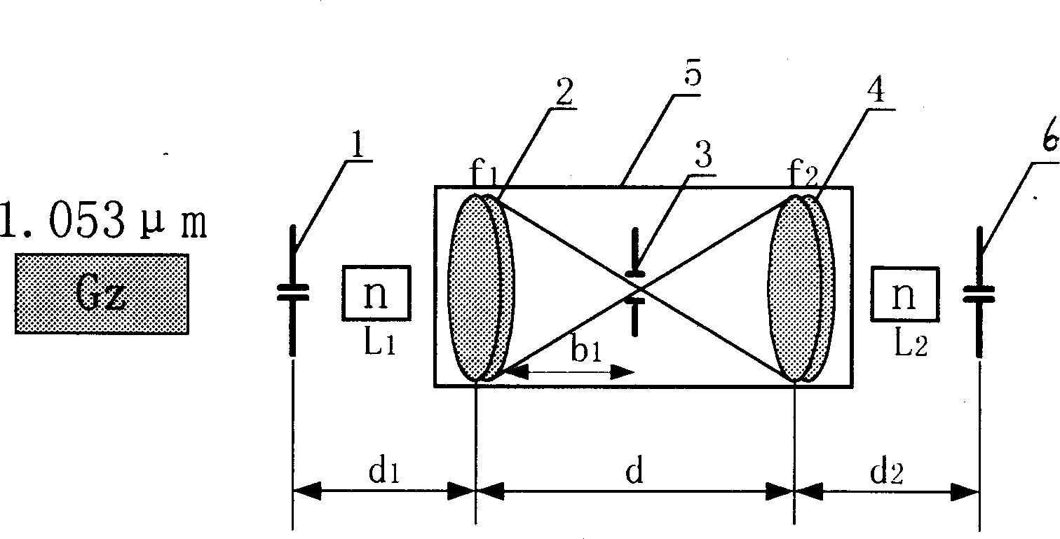
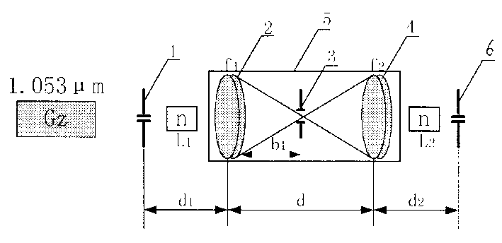
[0026] Please see first figure 1 , figure 1 It is a structural schematic diagram of an embodiment of the small hole real image transmission device of the present invention. The wavelength of the main laser Gz is 1.053μm, and the material of the circular hole aperture 1 is tantalum-tungsten alloy, the size is Φ20×2mm, and the aperture is Φ2.2mm. The aperture of the circular aperture aperture 1 varies with the size of the beam aperture And change. The material of input lens 2 and output lens 4 of spatial filter 5 is K 9 Glass. The size of the input lens 2 is Φ30×4mm, and the size of the output lens 4 is Φ50×5mm. Both the input lens 2 and the output lens 4 are double-convex spherical mirrors, and the two ends of the mirror are coated with a 1.05 μm high anti-reflection hard coating. The diameter and focal length of the input lens 2 and the output lens 4 are determined according to the diameter of the laser beam. The filter hole 3 is made of a tantalum-tungsten alloy with a l...


PUM


Abstract

The aperture real image transfer unit for the transmission in the high power laser system is composed of the circular aperture diaphragm, the spatial filter and the diaphragm with zigzag type soft edge. The spatial filter consists of the input lens, the filtering pinhole and the output lens. The filtering pinhole is positionted in the confocal point of the input lens and the output lens. The position relations of the said composed components satisfy the following expression: d2=dM-d1m2. The invention can eliminate astigmatism caused by virtual image transmission and restrain the diffraction modulation and the components of high frequency spectrum caused by the linear and nonlinear effects. The physical results are as following: laser beam near field fill factor is raised from 20-30% to 50%, the terminal is raised from 20-30 % to 50%, the quality of focal spot is 5 time better than the diffraction limit and the output energy is raised one time.

Description

Technical field: [0001] The invention relates to a laser system, in particular to a small hole real image transmission device. Background technique: [0002] The NIF laser system in the United States uses a spatial filter for image transfer technology, (see prior art [1] Suppression of Self-focusing through relay imag img and low pass Spatiarl filtering. Aimual Reports of LLN11998). During the amplification process of the laser through the working material and optical components, the diffraction and low-frequency modulation caused by linear and nonlinear effects will deteriorate the quality of the laser. The spatial filter technology is used to suppress the nonlinear growth of high-frequency components, and the spatial filter pitch is used for image transmission, and the image plane is designed in the laser working material to prevent the occurrence of self-focusing filaments, because the diffraction modulation on the image plane is the smallest. After the initial image pla...

Claims


Application Information

Patent Timeline
Patent Type & Authority Applications(China)
IPC IPC(8): G02B27/46H01S3/00
Inventor 张明科张臻朱俭范滇元马伟新
Owner SHANGHAI INST OF OPTICS & FINE MECHANICS CHINESE ACAD OF SCI
Why Eureka
Try Eureka