Battery and electric double-layer capacitor

A technology of batteries and current collectors, applied in the manufacture of double layer capacitors, multiple hybrid/electric double layer capacitors, and hybrid/electric double layer capacitors, etc., to achieve the effect of small equipment, prevention of terminal corrosion, and less production time

Inactive Publication Date: 2003-08-06
ENVISION AESC ENERGY DEVICES LTD
View PDF4 Cites 14 Cited by
  • Summary
  • Abstract
  • Description
  • Claims
  • Application Information

AI Technical Summary

Problems solved by technology

Therefore, there is room for improvement in reducing the size of products to produce batteries or capacitors with desired voltage or withstand voltage

Method used


Image

  • Battery and electric double-layer capacitor
  • Battery and electric double-layer capacitor
  • Battery and electric double-layer capacitor

Examples


Embodiment 1

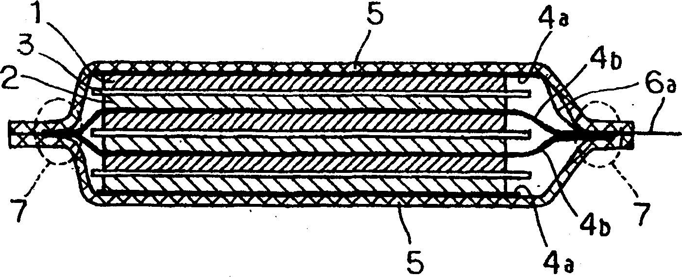
[0050] In this example, if figure 2 The battery shown was fabricated with a laminated structure of three elementary cells connected in series.

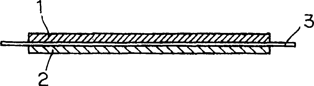
[0051] For the cathode 1, through the indole trimer represented by the chemical formula (1) (R at the 5-position of the indole cell is -CN and the remaining R is -H: 5-cyanoindole trimer ) to the cathode active material, add conductor auxiliary material and binder, stir or mix by mixer to form electrode powder, put 0.5 g of powder into mold and heat treatment to form 10cm 2 solid electrode.

[0052] For the anode 2, by adding the conductor auxiliary material in the anode active material of polybenzoquinoxaline represented by chemical formula (2), stirring or mixing by a mixer to form an electrode powder, by putting 0.5 gram of powder into molded and heat-treated to form a 10cm 2 solid electrode.

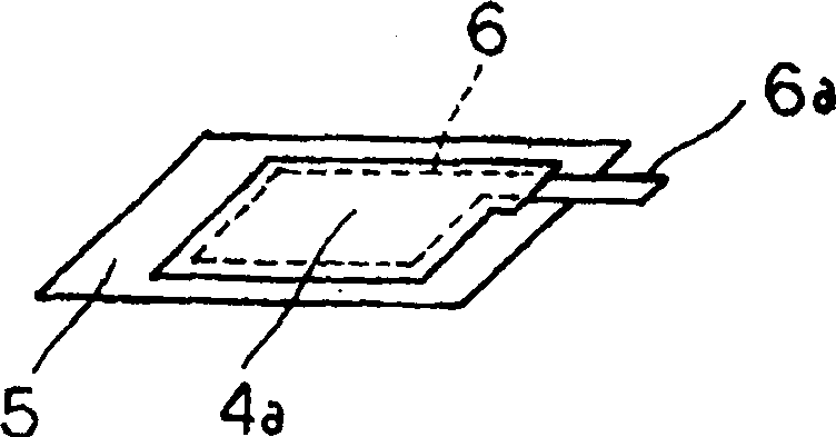
[0053] The current collectors 4a, 4b are conductive rubber thin layers and the laminated thin layer 5 is formed by laminating aluminum...

Embodiment 2

[0061] The battery manufactured in this example is as described in Example 1 except that the weight of the cathode and the anode are both 1.0 g.

[0062] The volumetric efficiency of the battery of Example 2 was 87.5%. The ESR of the battery is 120m. The time taken until the sealing process in the production process of the battery was 20 minutes. In the configuration of the present embodiment, volumetric efficiency is improved; ESR of a single cell can be reduced; and production time can be reduced.

Embodiment 3

[0064] The battery fabricated in this example was as described in Example 1, except that ten basic single cells were laminated in series and sealed.

[0065] The volumetric efficiency of the battery of Example 3 was 90.5%. The ESR of the battery is 200m. The time taken until the sealing process in the production process of the battery was 20 minutes. In the configuration of the present embodiment, volumetric efficiency is improved; single cell ESR can be reduced; and production time can be reduced.


PUM


Abstract

This invention provides a small battery and an electric double layer capacitor exhibiting adequate cell voltage and capacitor withstand voltage. Specifically, this invention provides a battery or electric double layer capacitor in which basic cells comprising a pair of electrodes oppositely laminated via the separator, and an electrolyte are packaged in a resin sheet package, wherein the basic cells are laminated in series via a sheet current collector; the sheet current collector extends to an edge of the resin sheet package around the periphery of the basic cells laminated on both sides of the current collector; the sheet current collector is glued or fused to the resin sheet in its edge; and the adjacent basic cells via the sheet current collector are fluid-tightly separated within the resin sheet package.

Description

technical field [0001] The present invention relates to a battery and an electric double layer capacitor encapsulated in a resin thin layer. Background technique [0002] Recently, reductions in size and weight of mobile devices used in information communication have led to greater efforts to develop smaller and lighter batteries and electric double layer capacitors capable of rapid charging / discharging. [0003] To meet the demand for smaller and lighter batteries and electric double layer capacitors, laminated films consisting of polymer film layers and metal foil layers are proposed as outer packaging materials. In order to improve quick charging / discharging characteristics, a metal plate such as a copper plate having a lower resistance is used as a terminal. [0004] Japanese Patent Publication No. 8-83596 discloses a thin card battery in which a sealed battery case composed of a laminated film includes a cathode, a separator, an anode and an electrolyte of the laminate...

Claims


Application Information

Patent Timeline
Patent Type & Authority Applications(China)
IPC IPC(8): H01GH01G9/00H01G9/08H01G9/10H01G11/10H01G11/12H01G11/22H01G11/42H01G11/52H01G11/66H01G11/70H01G11/72H01G11/74H01G11/78H01G11/82H01G11/86H01MH01M4/64H01M6/04H01M6/12H01M6/40H01M6/42H01M6/46H01M10/00H01M10/04H01M50/529H01M50/557H01M50/562
CPCY02E60/12H01G9/155H01M2/0212H01M10/0436H01M6/12Y02E60/13H01G9/10Y02E60/10H01M50/557Y02P70/50H01G11/72H01G11/80H01G11/12H01M50/562H01G11/78H01M50/124H01M50/116
Inventor 信田知希西山利彦纸秀浩幸原田学黑崎雅人中川裕二三谷胜哉
Owner ENVISION AESC ENERGY DEVICES LTD
Why Eureka
Try Eureka