Magnet switch for starter

A magnetic switch and starter technology, applied in the field of starters, to achieve the effects of increased life, improved reliability, and improved performance

Inactive Publication Date: 2003-10-15
DENSO CORP
View PDF3 Cites 8 Cited by
  • Summary
  • Abstract
  • Description
  • Claims
  • Application Information

AI Technical Summary

Problems solved by technology

Therefore, brushes are not preferred as contacts

Method used


Image

  • Magnet switch for starter
  • Magnet switch for starter
  • Magnet switch for starter

Examples


Embodiment Construction

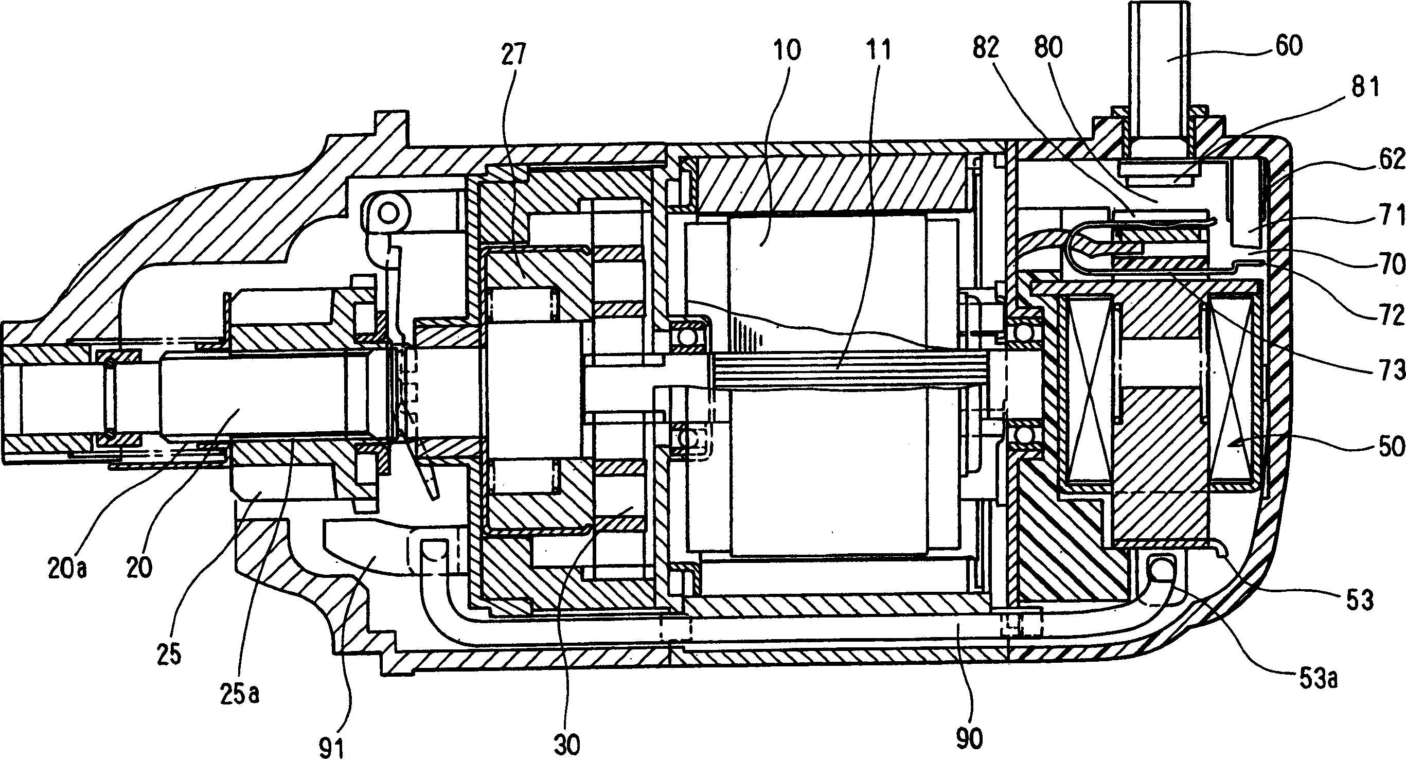
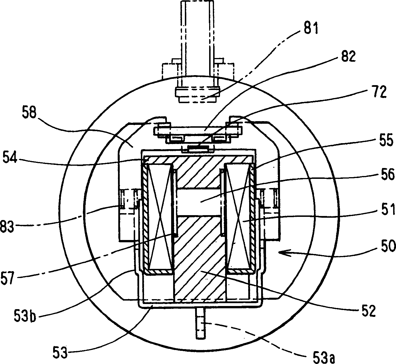
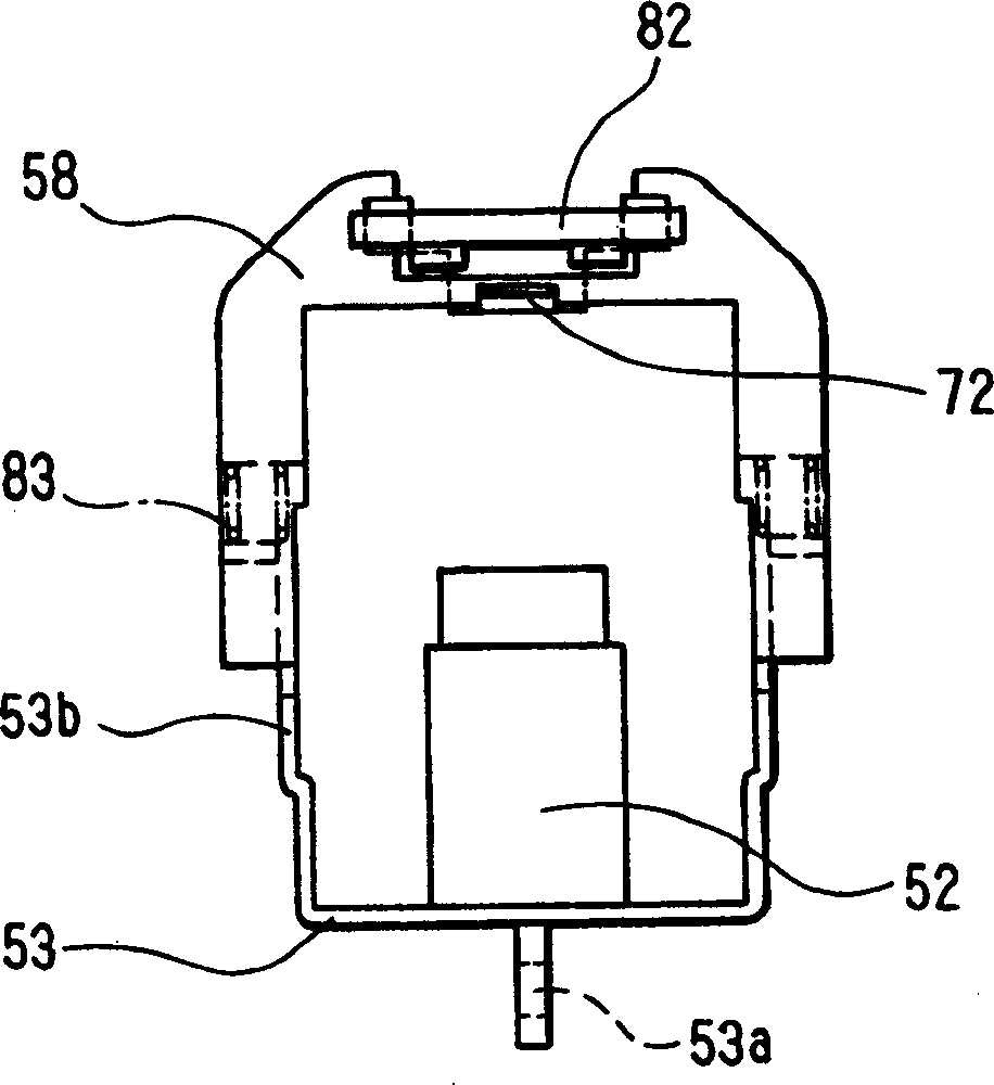
[0033] will be based on Figure 1-4 The embodiment shown in describes the starter of the present invention. Reference numeral 50 denotes a switch having an attracting coil 51 generating an electromagnetic force, a plunger 52 included in a magnetic circuit, a case 55 , a cover 54 , and an air gap 56 .

[0034] Reference numeral 70 denotes a first contact portion constituted by a fixed contact 71 and a movable contact 72 . The fixed contact 71 is made of a carbon material comprising one hundred percent carbon or mainly carbon with a small amount of metal content. The movable contact piece 72 is part of the first elastic member 73 . The first elastic member 73 is made of a material having electrical conductivity and mechanical strength, such as phosphor bronze.

[0035] Reference numeral 80 denotes a second contact portion constituted by a fixed contact 81 and a movable contact 82 . The first contact portion 70 and the second contact portion 80 are connected in parallel betwe...


PUM


Abstract

In a magnet switch for a starter, a first contact portion and a second contact portion are connected in parallel between a battery and a motor. The first contact portion makes contact through a resistive component so that the motor starts rotation at low speed. By this, a pinion is pushed in an axial direction by an axial component of splines and brought into mesh with a ring gear in a condition that its rotation is restricted. Thereafter, the second contact portion makes contact in accordance with further movement of a plunger so that electric power is fully supplied to the motor through the second contact portion, thereby starting engine. A fixed contact of the first contact portion is made of a carbon material. The resistive component is provided by the carbon material.

Description

technical field [0001] The invention relates to a starter for starting an internal combustion engine. More specifically, the present invention relates to a magnetic switch for a starter. Background technique [0002] Various efforts have been made to cope with recent environmental problems in the automotive field. Having said that, vehicle starters need various improvements, such as compactness, weight reduction, and resistance to long-term wear of the engine's idle limit (for fuel-efficient driving competitions). In order to meet this requirement, the starter disclosed in JP-A-9-68142 (USP 5,525,947) reduces damage to the ring gear by improving the meshing of the pinion gear. In addition, the starter can be finely controlled electronically by reducing the switching current. That is, electric power is supplied to the secondary contact through the resistance, so that the motor starts rotating at a low speed, and the pinion gear meshes with the ring gear with the rotating f...

Claims


Application Information

Patent Timeline
Patent Type & Authority Applications(China)
IPC IPC(8): F02N15/06F02N11/00F02N11/08H01H1/02H01H9/38H01H9/42H01H50/54H01H51/06
CPCF02N2300/102H01H51/065F02N11/0851F02N2011/0874F02N11/087F02N15/067H01H50/543H01H9/38H01H50/00
Inventor 志贺孜新美正已
Owner DENSO CORP
Why Eureka
Try Eureka