
Optical method for real time latent image self-moritoring in holographic raster mfg

A holographic grating and optical method technology, which is applied in the optical field for real-time latent image self-monitoring, can solve the problems of difficulty in determining the direction of incident light and diffracted light, complex and expensive real-time monitoring methods for latent images, and insufficient monitoring curve characteristics. Improved operability, high energy density, easy signal effects

Inactive Publication Date: 2003-10-22
TSINGHUA UNIV
View PDF0 Cites 10 Cited by
  • Summary
  • Abstract
  • Description
  • Claims
  • Application Information

AI Technical Summary

Problems solved by technology

In order to obtain relatively strong diffracted light, a short-wavelength laser is usually used for monitoring; since the photoresist has a strong absorption of short-wavelength, the incident light for monitoring must be attenuated to a safe energy intensity; in order to detect such a weak signal, it is also necessary Add a chopper to modulate the signal, but the general diffraction efficiency can only reach 10 -6 ~10 -7 This makes it difficult to determine the direction of the incident light and diffracted light, the actual operation is very inconvenient, and it is more sensitive to the fluctuation of background light and laser output power
Therefore, the previous real-time monitoring method of latent image is complicated, expensive, difficult to operate, and the characteristics of the obtained monitoring curve are not obvious enough, and it is basically still in the stage of laboratory exploration, and it is not practical yet.
In addition, so far, no technology has been reported to greatly improve the groove quality and production efficiency of holographic gratings

Method used


Image

  • Optical method for real time latent image self-moritoring in holographic raster mfg
  • Optical method for real time latent image self-moritoring in holographic raster mfg
  • Optical method for real time latent image self-moritoring in holographic raster mfg

Examples


Embodiment Construction

[0026] The present invention will be further described below in conjunction with accompanying drawing:

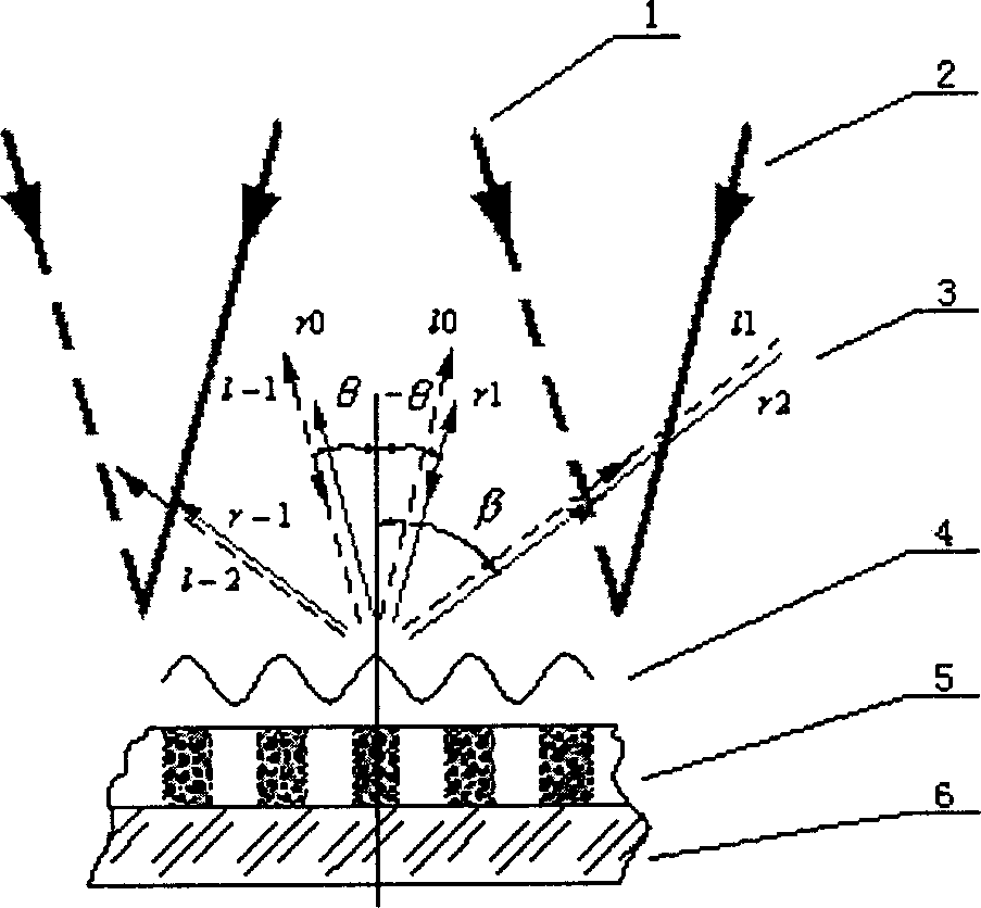
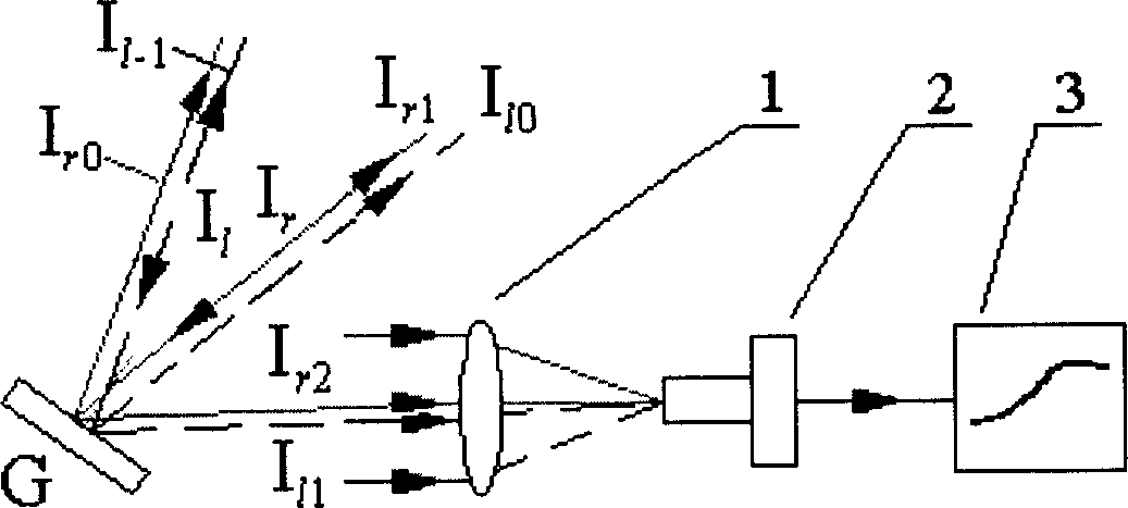
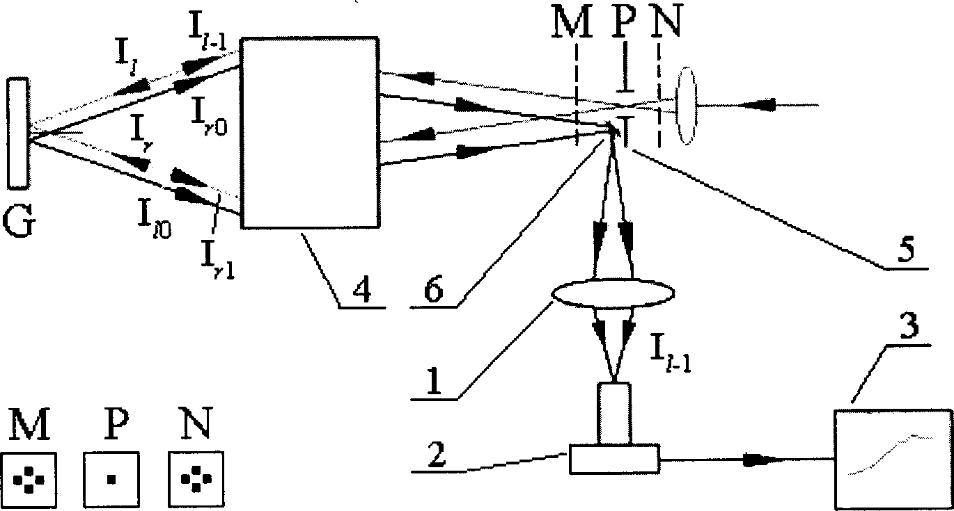
[0027] The present invention finds that the latent image produced by the photoresist during the exposure process has a "self-diffraction" phenomenon on the recording beam, such as figure 1 As shown, (1) is the incident light on the left, (2) is the incident light on the right, (3) is the self-diffraction order, (4) is the interference fringe, (5) is the latent image in the photoresist, ( 6) as the base. According to this fact, one of the optical methods of the real-time latent image self-monitoring usefulness in the holographic grating that the present invention proposes is that it uses the random interference recording light beam of the light intensity of the holographic grating as the incident light beam of the real-time latent image self-monitoring usefulness simultaneously, When the ratio of the wavelength of the incident beam to the period of the grating When , ther...


PUM


Abstract

The invention refers to a real-time latent-image self-monitoring method in the course of making a holographic grating. It uses arbitrary interference recording light beam of the light intensity acting on the grating as the real-time sub-image self-monotiring incident light beam, and when the ratio of the wavelength of the incident light beam and the period of the grating lambda / d<2 / 3, the gratinghas multiple diffraction levels, it real-time self-monitors the light beam outside the system collimated and photoelectricly multiplied in the transmission direction of self-diffractions Ir2 and Ir1 of arbitrary level sub-image, or real-timely self-monitors the autocollimating level returning according to the original route filtered, collimated and photoelectricaly multiplied.

Description

technical field [0001] The invention relates to an optical method for real-time latent image self-monitoring in the production of holographic gratings, in particular to an optical method for real-time latent image self-monitoring in the production of holographic gratings, which is widely used in the fields of spectroscopic instruments, measurement, optical information processing, and optical communication. Optical methods for monitoring. Background technique [0002] Diffraction gratings have a wide range of applications in many fields such as spectroscopic instruments, measurement, optical information processing and optical communication due to their unique wavefront segmentation and dispersion characteristics, and are often the core of the technology. At present, in scientific research and high-tech products, my country needs a large number of diffraction gratings, and the gratings with high quality and performance requirements basically rely on imports. There are many wa...

Claims


Application Information

Patent Timeline
IPC IPC(8): G02B5/18G02B5/32G03H1/04
Inventor 李立峰赵劲松吴振华
Owner TSINGHUA UNIV
Learn More