

Method for releasing oil field from blockage caused by high molecular polymer
A high molecular polymer, oil field technology, used in earth-moving drilling, production of fluids, wellbore/well components, etc., can solve the problems of increasing injection pressure, affecting crude oil production, and reducing the amount of injected liquid, to promote thermal degradation, The effect of protecting the blockage removal effect and reducing the treatment cost
- Summary
- Abstract
- Description
- Claims
- Application Information
AI Technical Summary
Problems solved by technology
Method used
Image

Examples
Embodiment 1
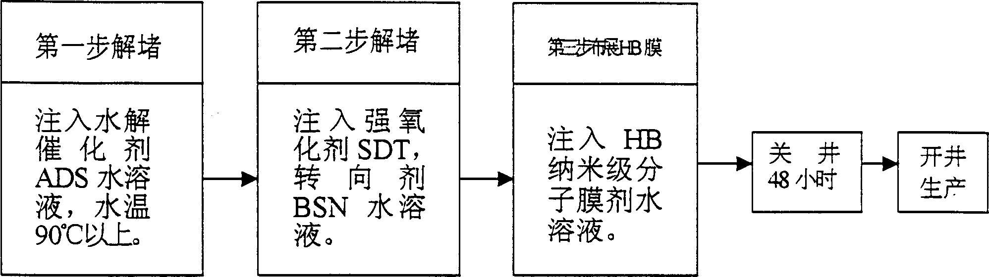
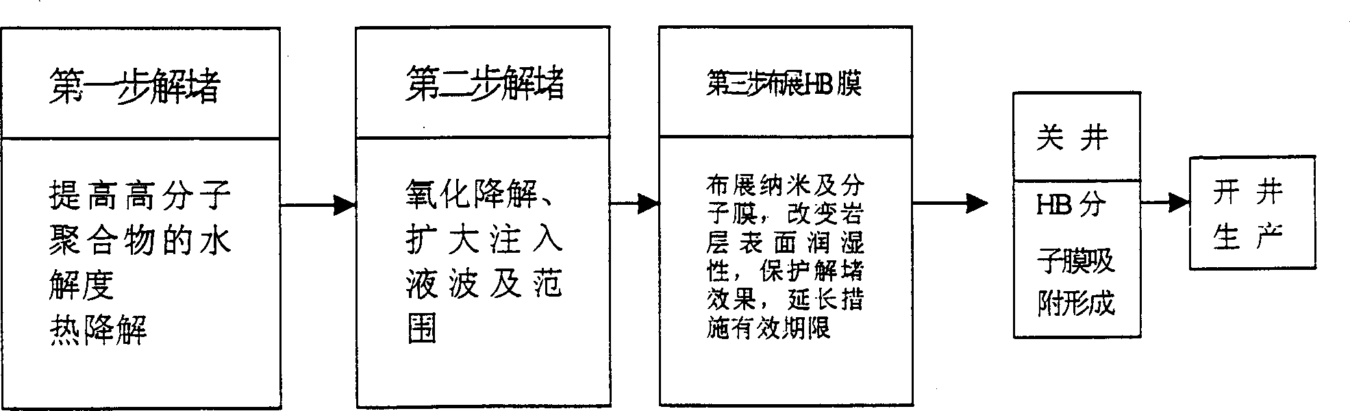
[0017] Embodiment 1: Treating a severely blocked polymer injection well, the effective thickness of the oil layer is h10 meters, the design treatment radius is r5 meters, and the porosity percentage of the oil layer is φ20%. Its plugging removal step: the first step is to inject 157 cubic meters of hydrolysis catalyst ADS 0.3%-1.2% sodium hydroxide aqueous solution into the unblocked oil layer with a pump, and the temperature is above 90°C. After the high molecular polymer is injected into the oil layer, thermal degradation reactions can usually occur at high temperatures, for example, hydrolyzed polyacrylamide begins to degrade above 85°C, and there will be obvious degradation at 90°C to 110°C. In the present invention The temperature of the injected solution is above 90°C, which can achieve a certain deblocking effect, and the presence of the catalyst sodium hydroxide can further increase the degree of hydrolysis of polyacrylamide, that is, the number of negatively charged ch...
Embodiment 2
[0019] Embodiment 2: Treating an obviously blocked polymer injection well, the effective thickness of the oil layer is h12 meters, the design treatment radius is r8 meters, and the porosity percentage of the oil layer is φ10%. Its plugging removal step: the first step is to inject 240 cubic meters of hydrolysis catalyst ADS 0.3%-1.2% potassium hydroxide aqueous solution into the unblocked oil layer with a pump, and the temperature is above 90°C. Then perform the second step of injecting 250 cubic meters of aqueous solution of nanomolecular film agent HB 0.1%-0.5% modified alkylsiloxane polyoxyethylene ether, and the solution temperature is normal temperature. During the unblocking process, the well was sealed for 48 hours.
Embodiment 3
[0020] Embodiment 3: Treating an obviously blocked polymer injection well, the effective thickness of the oil layer is h9 meters, the design treatment radius is r6 meters, and the porosity percentage of the oil layer is φ25%. Its plugging removal steps: the first step is to pump 254 cubic meters of strong oxidant SDT 0.1%-5% chlorine-containing polycyanic acid aqueous solution into the unblocked oil layer, the solution temperature is normal temperature, and add the steering agent BSN-sulfamic acid 9 Kilogram. In the second step, 254 cubic meters of aqueous solution of nanomolecular film agent HB 0.1%-0.5% modified alkylsiloxane polyoxyethylene ether is injected, and the solution temperature is normal temperature. During the unblocking process, the well was sealed for 48 hours.
[0021] In the present invention, the plugging removal step C can be carried out before step A, that is to say, it is carried out before the polymer injection well is flooded with high molecular polyme...
PUM
 Abstract
Description
Claims
Application Information