
Equipment and method for preparing fibre-optical microprobe by siphon lifting method corrosion

A micro-probe and siphon technology, applied in measurement devices, scanning probe technology, scanning probe microscopy, etc., can solve the problems of large human injury, strong HF acid corrosion, and unenvironmental protection, and it is easy to achieve preparation conditions. Control, good repeatability and ideal performance

Inactive Publication Date: 2004-03-17
SOUTHEAST UNIV
View PDF0 Cites 15 Cited by
  • Summary
  • Abstract
  • Description
  • Claims
  • Application Information

AI Technical Summary

Problems solved by technology

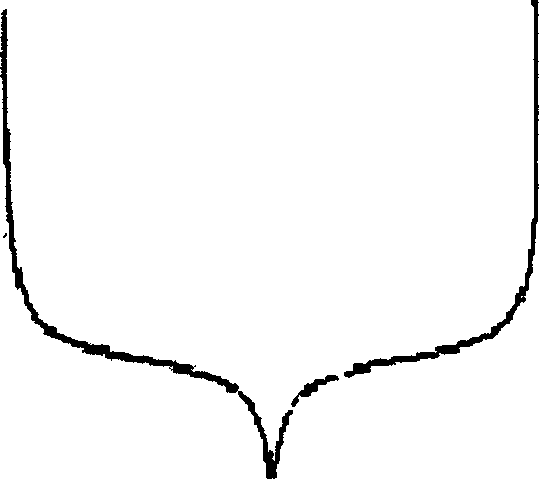
In order to prepare an "ideal" optical fiber probe with both cone shape and window size, some people combined heating stretching and chemical etching, that is, using the so-called "two-step" forming method to prepare a better general fiber probe. The parabolic cone shape with light efficiency and the ultra-sharp needle tip with better resolution, practice shows that such a needle tip can be realized, but the defects of high cost and inability to prepare different cone shapes are still unresolved, and worse Yes, this method of fabricating fiber optic probes is very poorly reproducible due to the combination of thermal stretching and elevated corrosion
Recently, some people use a liquid leakage device to insert a part of the bare optical fiber into the HF acid solution to fix the position of the optical fiber, and then let the HF acid slowly leak into another container, so as to achieve a relatively improved corrosion, and then obtain an optical fiber probe , this method reduces the cost of preparing the probe, and has most of the advantages of mechanical lifting corrosion. However, because HF acid is very corrosive and volatile, it is harmful to the human body and is not environmentally friendly.
Moreover, also like mechanical lifting corrosion, it is difficult to control the smooth and variable speed at any time, so it is impossible to prepare probes with different cone shapes
It is precisely because the current microprobe preparation method has defects such as relatively precise processing equipment, high processing cost of fiber optic probes, and unsatisfactory repeatability. Therefore, it is necessary to explore the preparation of high-performance near-field optical fiber probes. The improved method naturally becomes the center and hotspot of the current near-field optical microscope research work.

Method used


Image

  • Equipment and method for preparing fibre-optical microprobe by siphon lifting method corrosion
  • Equipment and method for preparing fibre-optical microprobe by siphon lifting method corrosion
  • Equipment and method for preparing fibre-optical microprobe by siphon lifting method corrosion

Examples


Embodiment Construction

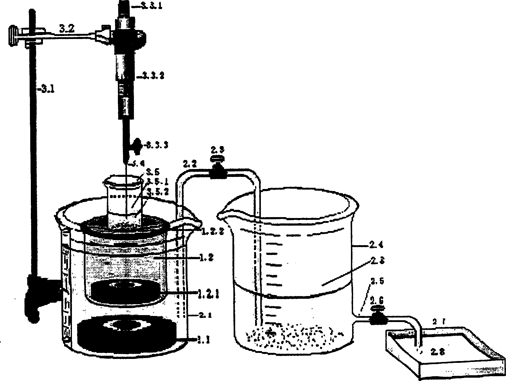
[0014] The device adopts magnetic force to position the suspended object stage, realizes gentle and variable lifting corrosion through siphon, and realizes a novel method for preparing optical fiber probe with multiple advantages. The device is composed of three main parts and an auxiliary part, namely the magnetic positioning of the suspended load, the siphon level control, and the optical fiber probe position control three main parts, and the optical lever initial speed measurement auxiliary part. The magnetic positioning suspended load system consists of a positioning magnet and a magnetic suspension stage; the siphon level control system consists of the main container (beaker), siphon tube, siphon flow rate control valve, attached container (beaker), drain pipe, drain control valve and The drainage tank is composed of; the optical fiber probe position control system is composed of an iron stand (with bracket), a spiral micrometer, an optical fiber fixing clip and a corrosive l...


PUM


Abstract

The apparatus and method for preparing optical fiber microprobe by siphon lifting corrosion process, wherein the method comprises, fixing one end of the optical fiber above the etching solution container, placing another end in the etching solution positioned in the etching solution container, which is suspended on the liquid level in the main siphon container, adjusting the siphon speed-regulating valve at the center of the siphon, making the liquid level of the etching solution in the etching solution container slowly leave the optical fiber mounted on the helical micrometer, etching required probe according to the predetermined falling speed. The method by the invention realizes low fabrication cost, better repeatability and simple process. íí

Description

1. Technical Field [0001] The invention relates to a method for preparing optical fiber probes for near-field optical microscopes, probes for near-field detectors, and micro-probes for microsensors, in particular to a device and method for preparing optical fiber micro-probes by etching with a siphon lift corrosion method . 2. Background technology [0002] There are many methods for preparing optical fiber probes for near-field optics, such as heating stretching, chemical etching, and electrolysis. In theory, the more mature methods are heating stretching and chemical etching. These two methods are also The method for preparing optical fiber probes in practical application at present. The heating drawing method is to heat a part of the single-mode optical fiber with laser or infrared, and simultaneously apply external force to the two ends to slowly draw outwards. As time goes by, the optical fiber is drawn and gradually becomes thinner, and finally disconnected. The tip of the ...

Claims


Application Information

Patent Timeline
IPC IPC(8): G01Q60/22
Inventor 顾宁孙龙李昌安刘战辉
Owner SOUTHEAST UNIV
Learn More