Heat exchanging type boiler

A boiler and water tank technology, which is applied in the field of heat exchange boilers, can solve the problems of boiler rupture, improvement, and long-term cleaning of water tanks or water pipes.

Inactive Publication Date: 2004-04-21
辛昶根
View PDF0 Cites 1 Cited by
  • Summary
  • Abstract
  • Description
  • Claims
  • Application Information

AI Technical Summary

Problems solved by technology

[0006] However, in conventionally used boilers, heat energy is largely consumed for raising the temperature of the water tank or water pipes through the water tank or water pipes, and due to the high thermal conductivity of the water tank or water pipes, heat energy is easily dissipated outside the boiler, which makes the boiler The thermal efficiency is greatly reduced
In addition, the convection of water in the tank or pipes is only used to increase the overall temperature of the water, so that the heating rate is very low and it is difficult to increase the thermal efficiency beyond a specified level
[0007] In addition, in order to expand the heat transfer area of ​​the water tank or water pipe, the water tank or water pipe is designed to be bent many times, which leads to high manufacturing cost
And because of the complicated structure, it takes quite a long time to clean the tank or the water pipes
[0008] Tanks or pipes have high thermal conductivity, but relatively low chemical resistance, making them easily exposed to corrosion
At the same time, the impurities in the water are combined to produce rust and adhere to the inner wall of the water tank, which greatly reduces the heat transfer efficiency
Therefore, the thermal expansion on the tank wall surface is not uniform and the boiler cracks
This results in a reduced life cycle of the boiler and frequent cleaning of the boiler interior

Method used


Image

  • Heat exchanging type boiler
  • Heat exchanging type boiler
  • Heat exchanging type boiler

Examples


Embodiment Construction

[0028] best practice

[0029] Preferred embodiments of the present invention will be described below in conjunction with the accompanying drawings.

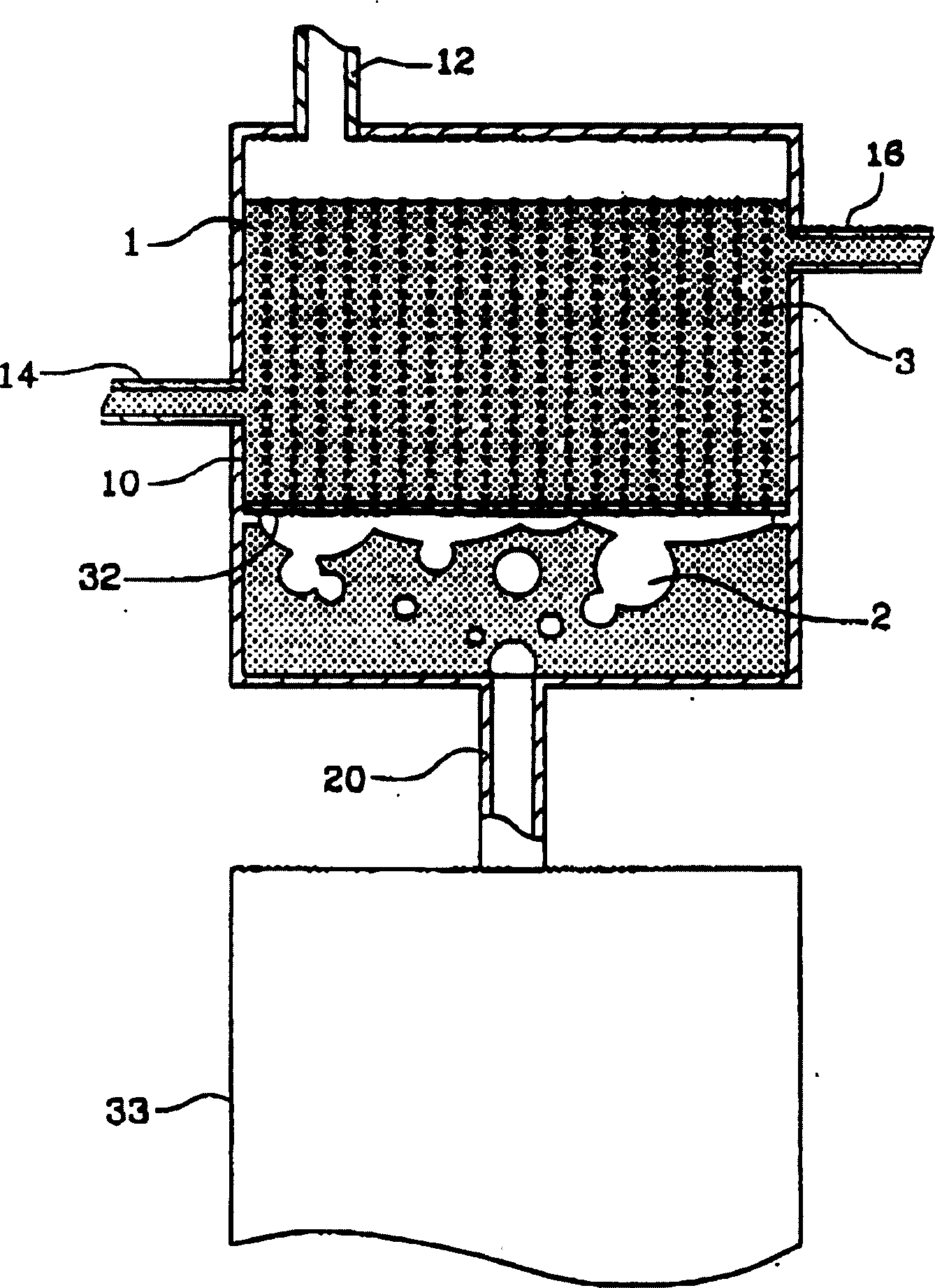
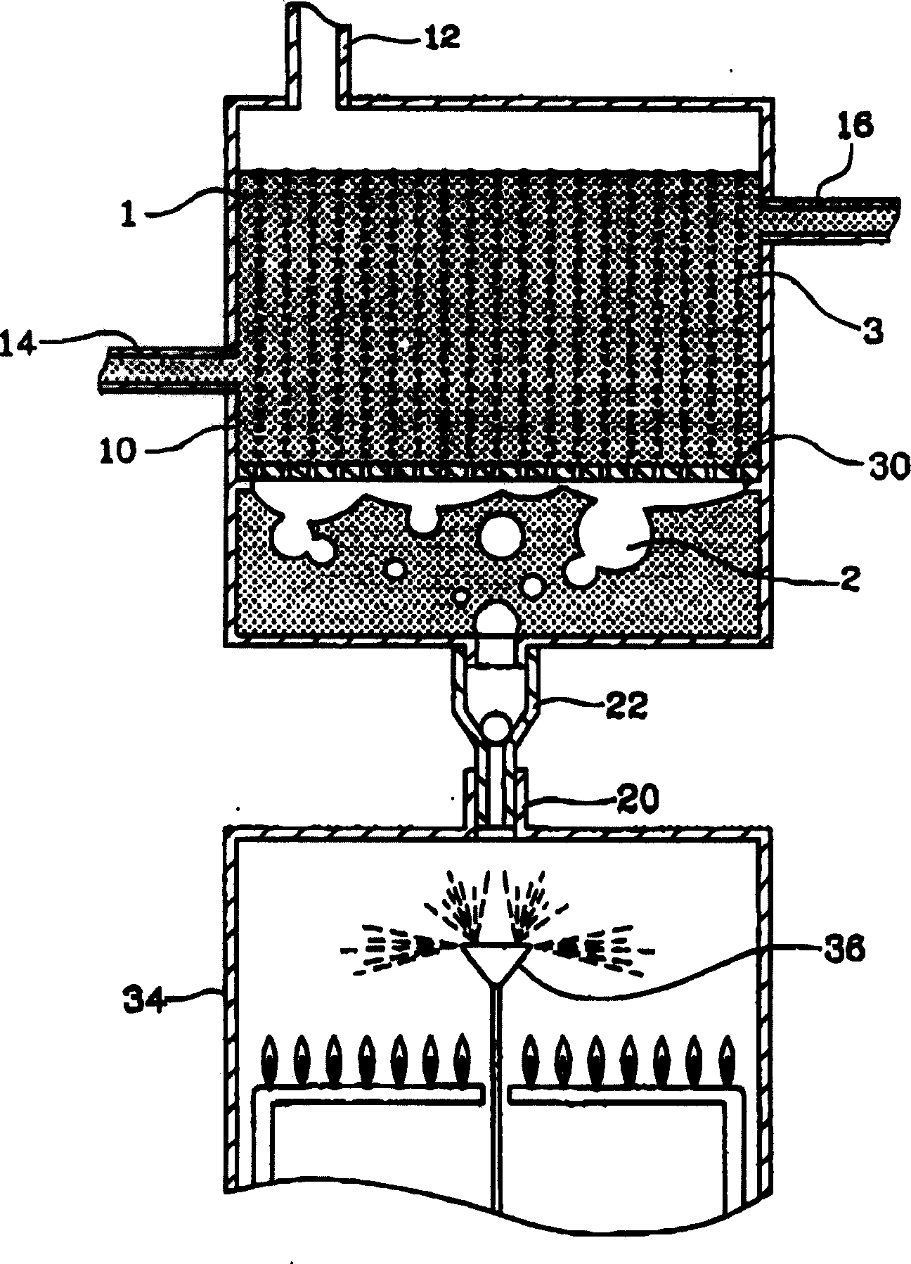
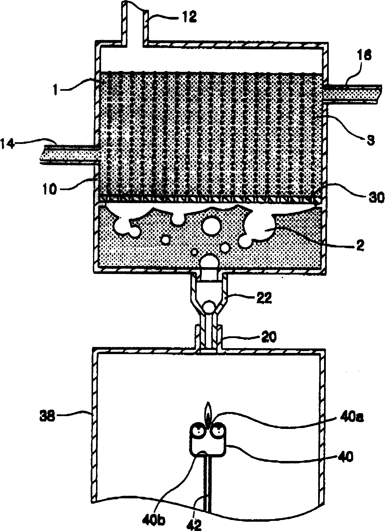
[0030] First refer to figure 1 , the first embodiment of the heat exchange boiler of the present invention includes a water tank 10 with a certain amount of water, and a combustible gas supply pipe 20 for providing bubbles of high-temperature combustible gas 2 in the water tank 10, and a drainage film 32 for dissolving The bubbles of the combustible gas 2 emitted from the combustible gas supply pipe 20 are dispersed in the form of very small bubbles 3 so that the contact area of ​​the bubbles of the combustible gas 2 can be expanded.

[0031] In this case, the water tank 10 is in the shape of a closed box, which has a steam discharge pipe 12 through which combustible gas and steam are discharged at the top plate, and a water supply pipe 14 for supplying water 1 at one side of the water tank 10 into the water tank 10, and the dr...


PUM


Abstract

The present invention relates to a heat exchanging type boiler that includes: a water retaining reservoir (10) in which a predetermined amount of water is charged; and a combustion chamber (33) for emitting heating gas at a high temperature to the water in the water retaining reservoir (10) through a heating gas supply pipe (20) such that the water in the water retaining reservoir (10) is raised to produce steam at a high pressure, the boiler characterized in that water discharging film (32) disposed between the heating gas supply pipe (20) and the water and having a plurality of fine through holes such taht the water in the water retaining reservoir (10) is not leaked to the combustion chamber (33) and at the same time the heating gas emitted to the water by means of the heating gas supply pipe (20) is distributed in substantially small bubble form. Thus, water heating speed can be considerably increased, heat efficiency of the boiler can be more improved, a volume of the boiler can be decreased, the life of the boiler can be semi-permanently extended since the water retaining reservoir is not directly heated, and the cleaning of the interior of the boiler can be carried out in an easy manner.

Description

technical field [0001] The invention relates to a heat exchange boiler, in particular to a heat exchange boiler which generates bubble-shaped combustible gas and makes the combustible gas contact with the water in the water tank to heat the water in the water tank. Background technique [0002] Generally speaking, a boiler is a device that heats water from inside or outside in a sealed tank in order to provide hot water or high-temperature and high-pressure steam. High-temperature water or steam is used to heat buildings, while high-pressure water or steam is used to start steam turbines in thermal power plants to generate electricity. [0003] In order to reduce a large amount of waste heat other than the heat consumed for heating water, various studies have been conducted on boilers. Recently, a booster boiler is provided for supplying compressed air in a combustion chamber to improve combustion efficiency in the combustion chamber. [0004] Typically, a conventionally d...

Claims


Application Information

Patent Timeline
Patent Type & Authority Applications(China)
IPC IPC(8): F22B1/18F22B1/26
CPCF22B1/26F22B1/1853
Inventor 辛昶根
Owner 辛昶根
Why Eureka
Try Eureka