Trace amount liquid viscosity measuring method and apparatus

A technology of trace liquid and measurement method, applied in the field of viscosity instruments, can solve the problems of unsuitable micro-flow liquid viscosity, high cost of constant temperature bath, large amount of experimental liquid, etc., achieving short measurement period, suitable for miniaturization, and liquid small amount of effect

Inactive Publication Date: 2004-06-02
INST OF MECHANICS - CHINESE ACAD OF SCI
View PDF0 Cites 15 Cited by
  • Summary
  • Abstract
  • Description
  • Claims
  • Application Information

AI Technical Summary

Problems solved by technology

[0011] The purpose of the present invention is to: overcome above-mentioned existing liquid viscosity measurement method because the capillary tube that uses is thick and cause the experiment liquid consumption to be big, be no...

Method used


Image

  • Trace amount liquid viscosity measuring method and apparatus
  • Trace amount liquid viscosity measuring method and apparatus
  • Trace amount liquid viscosity measuring method and apparatus

Examples


Embodiment 1

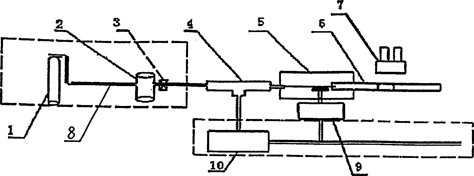
[0043] according to figure 1 To make a trace liquid viscosity measuring instrument, the gas storage cylinder 1 adopts a nitrogen cylinder, which communicates with the liquid storage tank 2 through a pipeline 8, and the liquid storage tank 2 is filled with water, and is connected to the tee 4 through the valve 3, and the two ports of the tee 4 Connect with the pressure sensor 10 and the micron pipe 14 bought in the market respectively; The other port of the glass displacement tube 5 of the displacement tube 6 passes through the temperature controller 5 and is directly connected to the atmosphere; the thermocouple 12 purchased in the market is placed close to the position of the micrometer pipe sleeve 13 wall, and measures the temperature in the sleeve cavity; The optical microscope 7 is arranged above the displacement tube 6 .

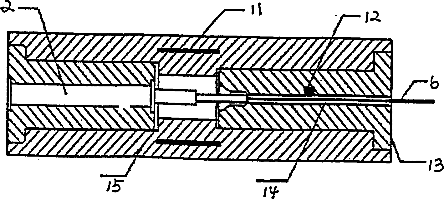
[0044] according to figure 2 To make a miniature adjustable constant temperature device for viscosity measurement, a rectangular copper plate with a l...

Embodiment 2

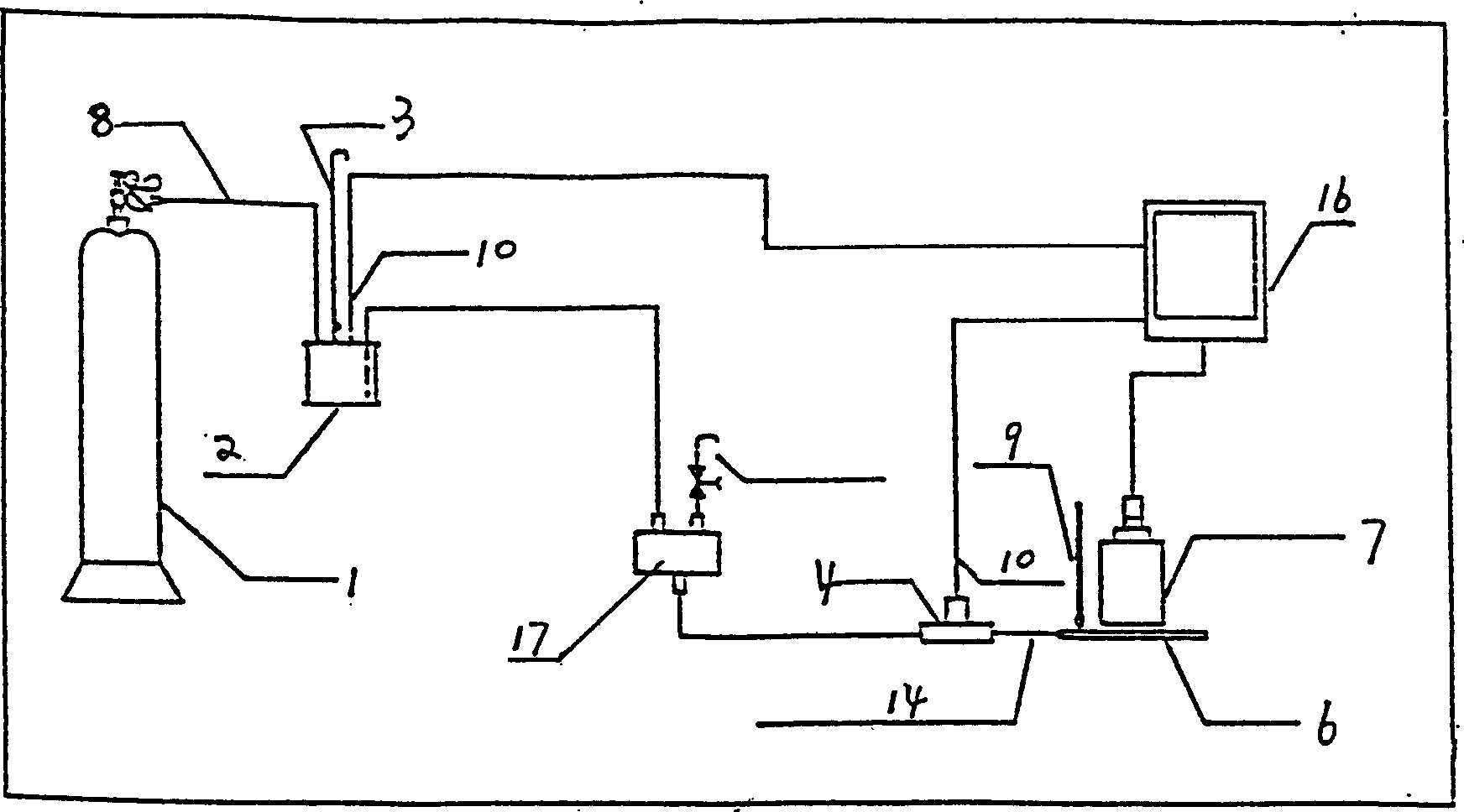
[0046] On the basis of embodiment 1, also increase computer 16, it is electrically connected with thermocouple 12, pressure sensor 10 and optical microscope 7 in temperature controller 5; Increase filter between liquid storage tank 2 and quartz tube 14 17. The filter membrane aperture is 0.2 μm, and the gas storage bottle 11, the liquid storage tank 2, and the filter 17 are connected with a high-pressure resistant plastic hose, and the joint adopts a hard seal.

Embodiment 4

[0051] Use the trace liquid viscometer in embodiment 2, in the scope of 10~40 ℃, measure the viscosity coefficient of carbon tetrahalide, carbon tetrahalide is housed in the liquid storage tank, the experiment adopts the nitrogen bottle of internal pressure 10Mpa and internal diameter is 25 μ m , A pipe with an outer diameter of 320μm and a length of about 4.7cm, with a pressure of 0.2Mpa. Measuring method and process are the same as embodiment 3. The experimental results show that: at the set target temperature, the viscosity measurement result is close to the theoretical value, and the error is only 0.6%-3.2%.


PUM

PropertyMeasurementUnit
Membrane pore sizeaaaaaaaaaa
The inside diameter ofaaaaaaaaaa
Outer diameteraaaaaaaaaa

Abstract

The present invention relates to micro liquid viscosity measuring method and unit. The present invention measures the viscosity of liquid indirectly via measuring the flow rate-pressure relationship of liquid in micron pipe, and the method is superior to available one, which adopts large amount of test liquid and expensive constant temperature bath. One micro liquid viscosity measuring instrument with small amount of test liquid, simple constant temperature device and short measurement period is provided. The measuring instrument consists of low pressure micro flow experimental apparatus and temperature controller, and has the structure including gas storage, liquid tank, T-pipe, pressure detector, temperature controller, micron pipeline inside the temperature controller, transparent displacement pipe with one end connected to the micron pipeline and the other end communicated to atmosphere via the temperature controller, and optical microscope on the transparent displacement pipe.

Description

technical field [0001] The invention relates to a method for measuring the viscosity of a trace liquid, in particular to an instrument for measuring the viscosity of a trace liquid. Background technique [0002] Viscosity is an important physical characteristic of fluid, which is the degree of viscosity, also known as dynamic viscosity. Viscosity measurement is very closely related to fields such as petrochemical, metallurgical coal and national defense. In these fields, viscosity measurement is an important means to control the production process, realize safe production, improve product quality, save and develop energy. In the medical field, measuring the viscosity of blood and other physiological fluids is a newly developed diagnostic method, especially for cardiovascular diseases, cancer, tumors and other difficult diseases. In scientific fields such as physical chemistry and fluid mechanics, viscosity measurement plays an important role in understanding fluid properti...

Claims


Application Information

Patent Timeline
IPC IPC(8): G01N11/00G01N11/08
Inventor 李战华覃裕平刘宗源
Owner INST OF MECHANICS - CHINESE ACAD OF SCI
Why Eureka
Try Eureka