Wear-resistant sliding member

A sliding part, external sliding technology, applied in the direction of engine components, machines/engines, coatings, etc., can solve problems such as attack, cylinder liner wear, etc., achieve low attack, prolong engine life, excellent wear resistance and friction resistance The effect of injury

Inactive Publication Date: 2004-06-02
NIPPON PISTONRING CO LTD +1
View PDF1 Cites 8 Cited by
  • Summary
  • Abstract
  • Description
  • Claims
  • Application Information

AI Technical Summary

Problems solved by technology

Moreover, there is also the problem that the ceramic powder attacks the matching material, causing the cylinder liner to wear

Method used


Image

  • Wear-resistant sliding member
  • Wear-resistant sliding member
  • Wear-resistant sliding member

Examples


Embodiment

[0020] Now, embodiments of the sliding member according to the present invention will be further described in conjunction with various tests conducted for comparison with other sliding members.

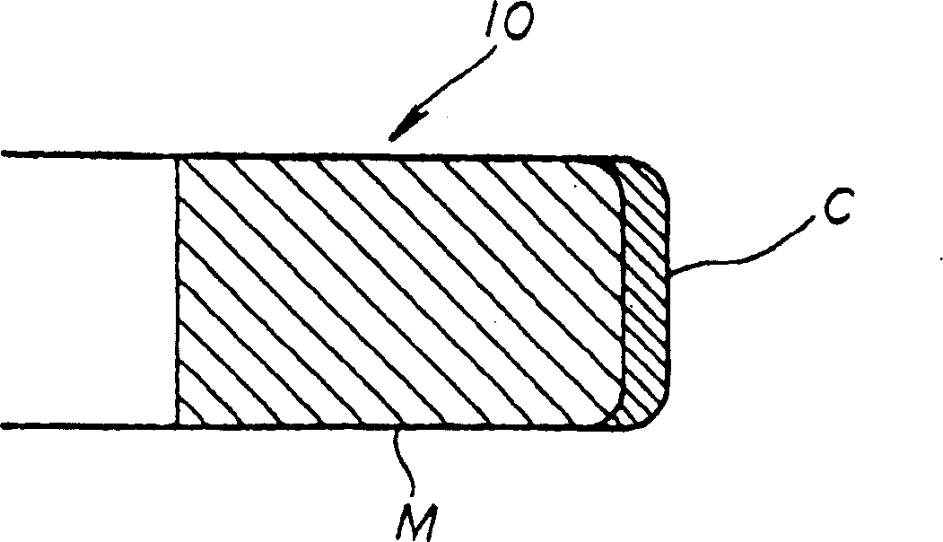
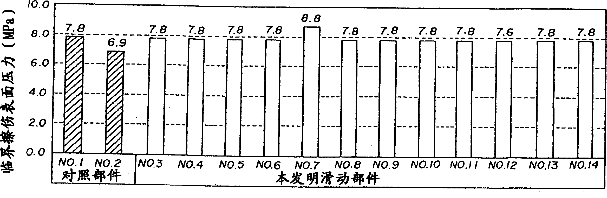
[0021] 14 types of 300 μm thick coatings were formed on the same cast iron segment used for piston rings (as the base material), and 14 samples were prepared, of which two samples 1 and 2 were controls or corresponded to the preceding Other sliding parts described in the references, 12 samples 3, 4, 5, 6, 7, 8, 9, 10, 11, 12, 13 and 14 are according to the invention or correspond to the respective embodiments. The coatings were obtained by plasma spraying various powder mixtures whose compositions are shown in Table 1.

[0022] Table 1

[0023] Sample number Remarks Composition of powder mixture (% (mass))

[0024] Mo Ni-Cr Alloy Ceramic Solid Lubricant

[0025] 1 Control 45 20 35(CrC)

[0026] 2 Control 65 30 5(CrC)

[0027] 3 Example of the prese...


PUM


Abstract

A wear-resistant sliding member (10) which comprises a base metal (M) and a sprayed coating (C) formed by thermally spraying a mixed powder comprising, by mass, 30 to 70% of a molybdenum powder, 10 to 40% of a nickel-chrome alloy powder, 5 to 40% of a ceramics powder, and 2 to 15% of a solid lubricant onto a sliding surface of the base metal. The wear-resistant sliding member is excellent in wear-resistance and resistance to scuffing, and thus can be utilized in a large-sized marine diesel engine, which is used under severe conditions.

Description

technical field [0001] The invention relates to a wear-resistant sliding part such as piston rings and cylinder liners for internal combustion engines. Background technique [0002] Recently, there has been a strong demand for higher power and performance of internal combustion engines. Sliding parts such as piston rings and cylinder liners for internal combustion engines are subject to increasingly severe operating conditions, and therefore, each sliding part is required to have higher wear resistance and anti-galling performance. [0003] Traditionally, chrome plating has been used to increase the wear resistance of sliding parts. However, chrome-plating treatment cannot sufficiently improve the anti-scuffing performance of sliding parts, and therefore, this process tends to be replaced by spraying treatment. For example, JP6-221438 proposes a technique of forming a sprayed layer on the outer peripheral sliding surface of a piston ring by plasma spraying, wherein the spr...

Claims


Application Information

Patent Timeline
Patent Type & Authority Applications(China)
IPC IPC(8): F02F1/00C23C4/04C23C4/10F02F5/00F16J9/26
CPCC23C4/06C23C4/04
Inventor 高村浩行
Owner NIPPON PISTONRING CO LTD
Why Eureka
Try Eureka