Dry cleaning method for plasma reaction chamber

A plasma and reaction chamber technology, applied in cleaning methods and utensils, cleaning hollow objects, chemical instruments and methods, etc., can solve the problems of time-consuming preventive maintenance cycle, reduced production capacity, etc.

Inactive Publication Date: 2004-06-23
AU OPTRONICS CORP
View PDF0 Cites 14 Cited by
  • Summary
  • Abstract
  • Description
  • Claims
  • Application Information

AI Technical Summary

Problems solved by technology

However, this wet cleaning method is time consuming and preventive mainte

Method used


Image

  • Dry cleaning method for plasma reaction chamber
  • Dry cleaning method for plasma reaction chamber

Examples


Embodiment Construction

[0012] In order to make the above-mentioned purposes, features and advantages of the present invention more obvious and easy to understand, the preferred embodiments are specifically cited below, together with the accompanying drawings, and are described in detail as follows:

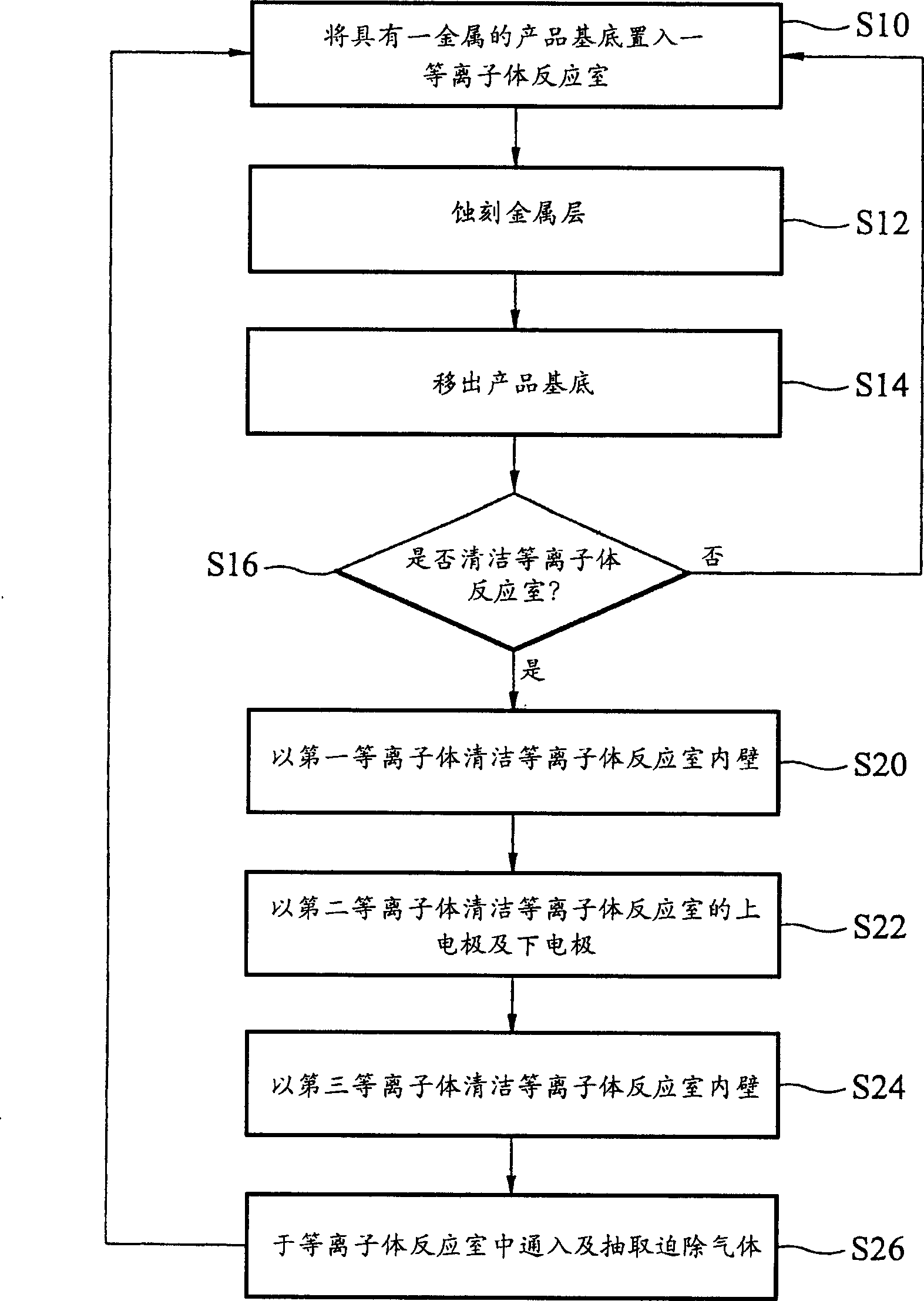
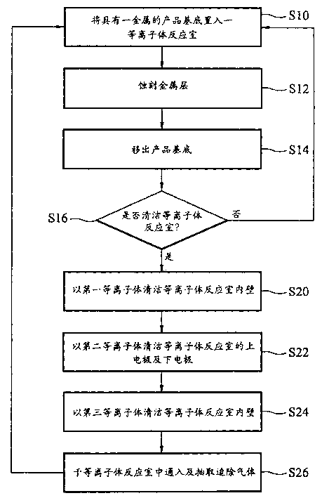
[0013] The dry cleaning method of the plasma reaction chamber according to the embodiment of the present invention will be described below with reference to FIG. 1 . Please refer to FIG. 1 , which shows a flow chart of a dry cleaning method after a metal etching process according to an embodiment of the present invention, which is applicable to a front-end array fabrication process of a TFT-LCD. Firstly, step S10 is performed to provide a product substrate, such as a glass substrate, on which a metal layer for making gate lines, such as molybdenum-aluminum-rubidium alloy, is formed. Next, a photoresist pattern layer is formed on the metal layer to define the pattern of the gate lines by means of a conve...


PUM


Abstract

The dry cleaning method for plasma reaction chamber is used in metal etching process. After one substrate with metal layer is set inside the plasma reaction chamber and its metal layer is etched, the dry cleaning process is completed after the substrate is removed from the plasma reaction chamber. Plasma formed with oxygen is first used to clean the inner wall of the plasma reaction chamber; plasma formed with chlorine and barium chloride gas is then used to clean the upper and lower electrode inside the plasma reaction chamber; plasma formed with sulfur fluoride gas and oxygen is used to clean the inner wall of the plasma reaction chamber; and oxygen and helium is finally introduced into and pumped from the plasma reaction chamber to remove gas.

Description

technical field [0001] The present invention relates to a cleaning method of a semiconductor device, in particular to a dry cleaning method of a plasma reaction chamber, so as to prolong the period of preventive maintenance (PM). Background technique [0002] Since plasma dry etching is used to etch metal to manufacture integrated circuit components, its performance is better than wet etching, so it has been widely used in the semiconductor industry or thin film transistor liquid crystal display (TFT-LCD) industry today. During the plasma dry etching process, a reactive gas is injected into a plasma chamber, and a plasma is formed by a radio frequency (radiation frequency, RF) electromagnetic wave as an etchant. [0003] When metal dry etching is performed in the reaction chamber, some etch by-products will be deposited on the inner wall of the reaction chamber. When these etching by-products accumulate on the inner wall of the reaction chamber to a certain extent, they wil...

Claims


Application Information

Patent Timeline
IPC IPC(8): B08B9/00C23F4/00H01L21/3065H01L21/3213
Inventor 郑朝云郭行健庄智强吴淑芬
Owner AU OPTRONICS CORP
Why Eureka
Try Eureka