Passive driving method for organic light emitting diodes
A light-emitting diode, passive drive technology, applied to instruments, static indicators, etc., can solve the problems of insufficient brightness and predicted value, current waste, parasitic capacitance charging, etc., and achieve the effect of shortening charging time, reducing rising time, and increasing rising rate
- Summary
- Abstract
- Description
- Claims
- Application Information
AI Technical Summary
Problems solved by technology
Method used
Image

Examples
Embodiment 1
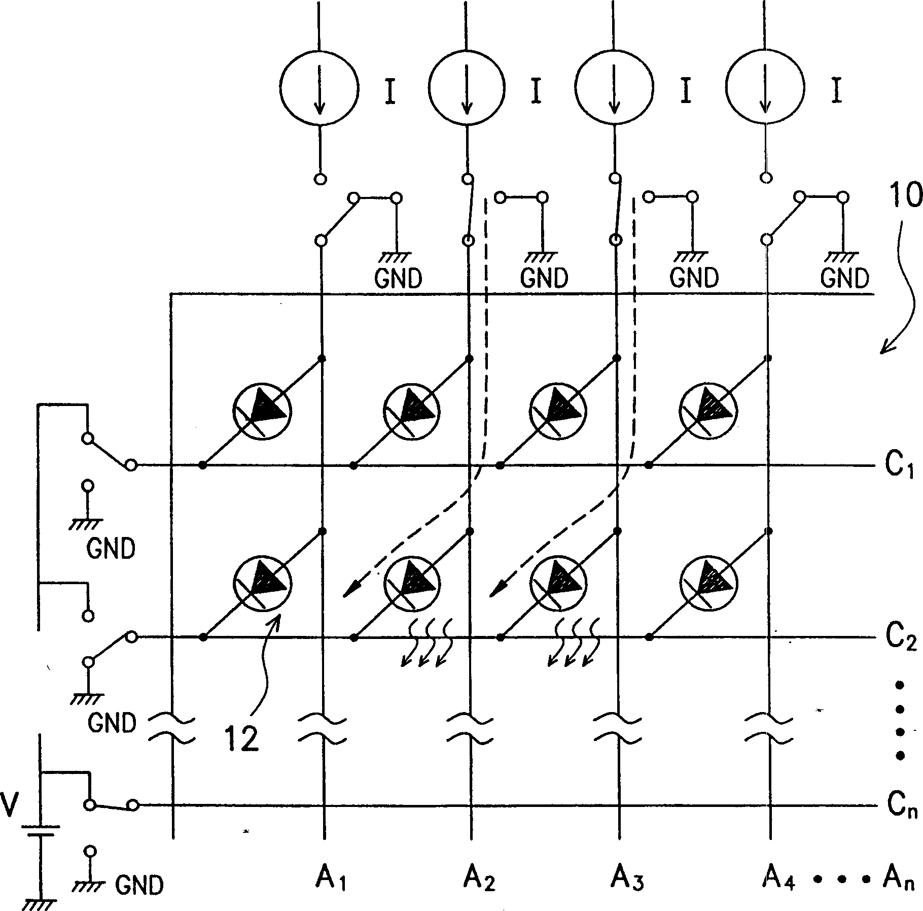
[0031]Please refer to FIG. 4, which is a schematic diagram of the passive driving circuit of the organic light emitting diode according to the first embodiment of the present invention. In FIG. 4, for the convenience of description, only a diagram of the relationship between one of the light-emitting diodes and the pre-charging circuit of the entire organic light-emitting diode array is shown. Those familiar with this technology know how to integrate into an entire organic light-emitting diode array.
[0032] As shown in FIG. 4, a pre-charging circuit 40 is electrically coupled to the anode of the organic light emitting diode 30. The anode of the organic light emitting diode 30 is connected to a fixed current source I and a voltage source V through the switch device 32. pp , And its cathode is connected to a reverse bias voltage V or ground GND through another switching device 34. When the organic light-emitting diode 30 is to be lit, the switching device 32 is turned off to allow...
Embodiment 2
[0041] Please refer to FIG. 6(A), which is a schematic diagram of a passive driving circuit of an organic light emitting diode according to a second embodiment of the present invention. In FIG. 6(A), for the convenience of description, only a diagram of the relationship between one of the light-emitting diodes and the pre-charging circuit of the entire organic light-emitting diode array is shown. Those familiar with this technology can know how to integrate an entire organic light-emitting diode In the array.
[0042] The difference between the second embodiment and the first embodiment is that the reference voltage V ref the design of. The functions and connections of the comparator 54 and the switching device 52 are the same as those of the first embodiment, and the description will not be repeated here, but only the reference voltage part will be described.
[0043] In the first embodiment, the reference voltage V ref It is adjusted and changed externally, so the reference volt...
Embodiment 3
[0050] Please refer to FIG. 7(A), which is a schematic diagram of a passive driving circuit of an organic light emitting diode according to a third embodiment of the present invention. In FIG. 7(A), for the convenience of explanation, only a diagram of the relationship between one of the light-emitting diodes and the pre-charging circuit of the entire organic light-emitting diode array is shown. Those familiar with this technology can know how to integrate an entire organic light-emitting diode In the array.
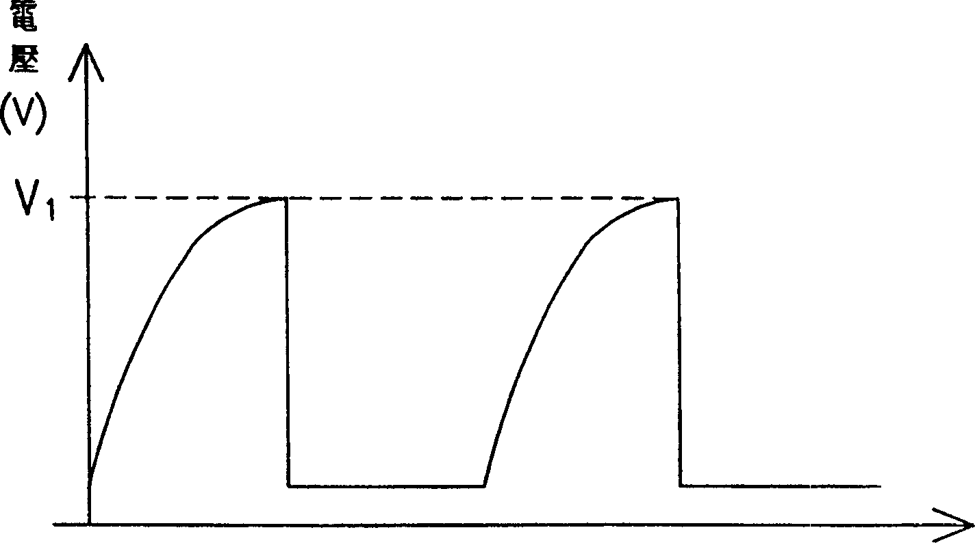
[0051] In both the first embodiment and the second embodiment, a fixed precharge voltage value is used to adjust the precharge time; that is, the precharge voltage V in FIG. 6(A) and FIG. 7(A) pp It is a fixed value. However, under this structure, the actual precharge time cannot be controlled, but is automatically controlled through a feedback mechanism. Therefore, when the uniformity of the anode voltage output is required to be very high, especially when the pulse-width-m...
PUM
 Abstract
Description
Claims
Application Information
 - R&D
- Intellectual Property
- Life Sciences
- Materials
- Tech Scout
- Unparalleled Data Quality
- Higher Quality Content
- 60% Fewer Hallucinations
Browse by: Latest US Patents, China's latest patents, Technical Efficacy Thesaurus, Application Domain, Technology Topic, Popular Technical Reports.
© 2025 PatSnap. All rights reserved.Legal|Privacy policy|Modern Slavery Act Transparency Statement|Sitemap|About US| Contact US: help@patsnap.com