Light splitting method for realizing Multipath output on laser phototypographic composing machine and its system

A laser phototypesetting machine and multi-channel output technology, which is applied in photoelectric typesetting devices, phototypesetting devices, printing, etc., can solve the problems such as the lack of mature laser channels, and achieve the effects of stable light intensity, good output quality, and increased output speed

Inactive Publication Date: 2004-07-21
HANGZHOU CRON MACHINERY & ELECTRONICS CO LTD
View PDF0 Cites 2 Cited by
  • Summary
  • Abstract
  • Description
  • Claims
  • Application Information

AI Technical Summary

Problems solved by technology

At present, the 4-channel light of the phototypesetter manufactured in China is relatively mature, but due to the limitation of the interaction between the acous

Method used


Image

  • Light splitting method for realizing Multipath output on laser phototypographic composing machine and its system
  • Light splitting method for realizing Multipath output on laser phototypographic composing machine and its system
  • Light splitting method for realizing Multipath output on laser phototypographic composing machine and its system

Examples


Embodiment Construction

[0024] Referring to the accompanying drawings, the present invention will be described in detail below.

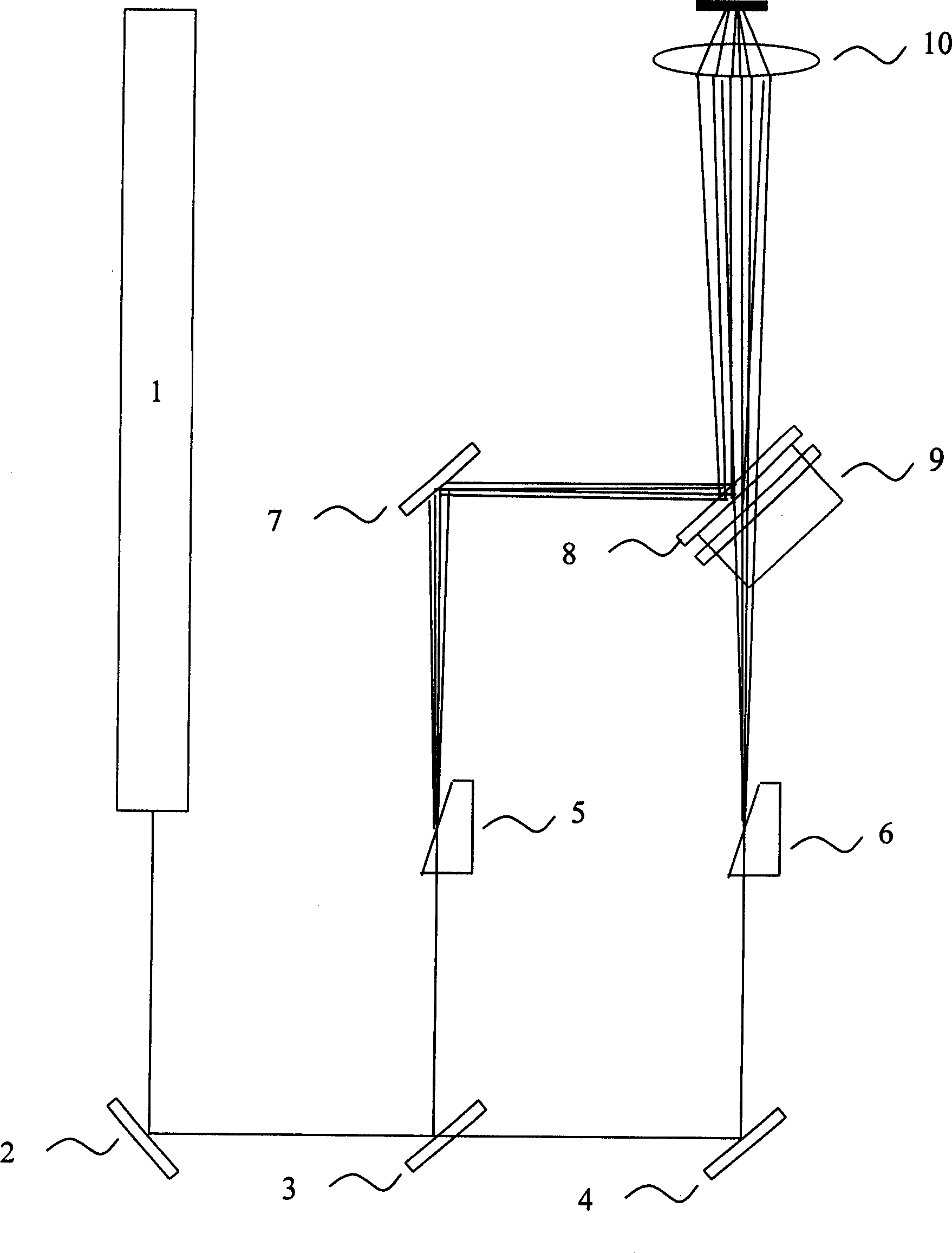
[0025] In the specific embodiment 1 of the present invention, the optical path of the light-fighting system is as follows: figure 1 shown.

[0026] The laser 1 emits a laser signal as a light source, and the reflector 2, which is at an angle of 135° to the axis of the laser tube, changes the route of the laser signal by 90°. The half-mirror 3 forms an angle of 45° with the axis of the laser tube. After the laser signal is projected onto its mirror surface, part of it is reflected to the acousto-optic modulator 5, and the other part is projected through the mirror to the half-mirror 3. On the parallel mirror 4, it is reflected to the acousto-optic modulator 6. At this time, the directions of the two laser signals are consistent and parallel.

[0027] The acousto-optic modulator is made of pure lead molybdate crystal. When a set of signals with a certain power and differen...


PUM


Abstract

A light-splicing method for implementing multi-channel output on laser typesetter to increase output speed is disclosed. A laser signal from the laser device is partially reflected to an acoustooptical modulator by a half-reflecting half-transmitting mirror. The transmitted laser signal is reflected to another acoustooptical modulator by reflector. According to control signal, the laser signal is diffracted into multiple channels of laser signal by said acoustooptical modulator. Said two laser signals are spliced by a half-reflecting half-transmitting to become the parallel channels of laser signal. Its system is also disclosed.

Description

technical field [0001] The invention relates to an electronic typesetting method and system thereof. More specifically, the present invention relates to a method and system for mosaicing multiple outputs on a laser imagesetter. Background technique [0002] Laser phototypesetting machine is a high-precision output laser imaging equipment. Laser phototypesetting machine uses helium-neon laser (or semiconductor laser) as the light source, and the graphic information and control signals control the work of the acousto-optic modulator through the interface circuit and the driving circuit signal source. , put the 4 (or 8) channels of the modulated first-order diffractive working laser light through the attenuation sheet, and focus them on the photosensitive film on the surface of the vacuum adsorption drum by the optical lens, and form 4 (or 8) channels of parallel light spots after focusing After the high-speed rotation of the optical drum and the horizontal synchronous movemen...

Claims


Application Information

Patent Timeline
IPC IPC(8): B41B19/00B41B21/08
Inventor 项建龙
Owner HANGZHOU CRON MACHINERY & ELECTRONICS CO LTD
Why Eureka
Try Eureka