Vehicle carried biware length scattering laser radar

A laser radar, dual-wavelength technology, applied in the measurement of scattering characteristics and other directions

Inactive Publication Date: 2004-12-22
ANHUI INST OF OPTICS & FINE MECHANICS - CHINESE ACAD OF SCI
View PDF0 Cites 22 Cited by
  • Summary
  • Abstract
  • Description
  • Claims
  • Application Information

AI Technical Summary

Problems solved by technology

[0010] The purpose of the present invention is to provide a vehicle-mounted dual-wavelength meter scattering laser radar (Dual WavelengthLidar is called for short DWL), which can be used for detection of atmospheric level visibility during the day and night; Its

Method used


Image

  • Vehicle carried biware length scattering laser radar
  • Vehicle carried biware length scattering laser radar
  • Vehicle carried biware length scattering laser radar

Examples


Embodiment Construction

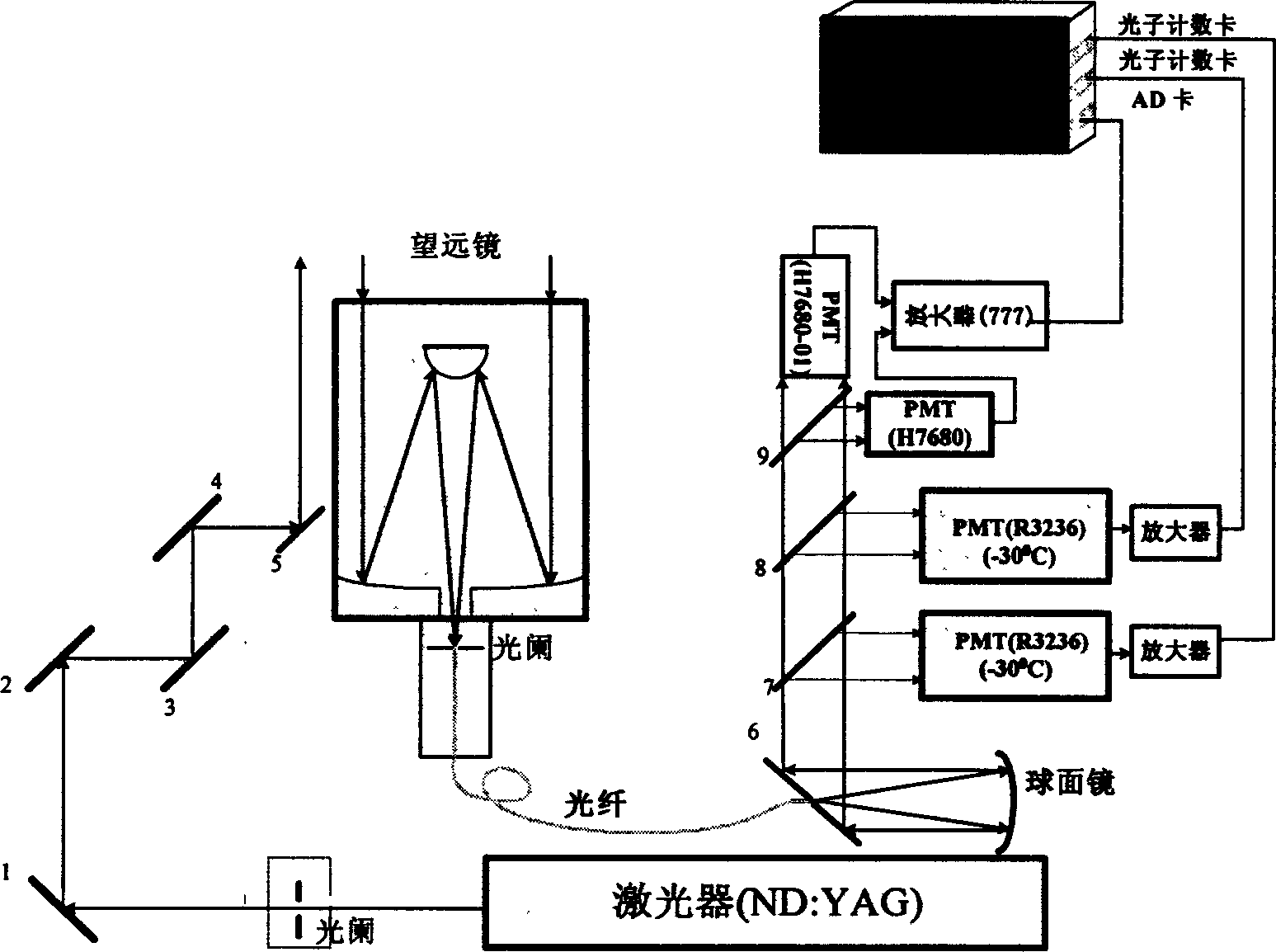
[0040] see figure 1 . The present invention is made up of following four units:

[0041] 1. Dual-wavelength laser emission unit

[0042] The function of the laser emitting unit is that when the receiving telescope is pitching, the laser beam can be kept equidistant from the optical axis of the receiving telescope and enter the atmosphere along a direction parallel to the optical axis.

[0043] The laser emitting unit includes a Nd:YAG laser, an aperture and a light guide system composed of 5 mirrors. A diaphragm and a total reflection mirror 1 are installed in front of the laser. After the laser is reflected by the total reflection mirror 1, it is reflected by four total reflection mirrors 2, 3, 4, and 5 that are parallel to each other and opposite to each other. The optical axis and the receiving telescope parallel.

[0044]The Nd:YAG laser is Brill from Quantel, France. It simultaneously outputs lasers with fundamental frequency 1064nm and double frequency 532nm. The si...


PUM


Abstract

The radar is composed of laser, receiving optical unit and followed optical unit, signal detection and data acquisition unit as well as system operation control unit. Frequency doubling head is setup on laser, and optical axis of receiving telescope is parallel to direction of laser light. Received optical signal on diaphragm in back of telescope through optical fiber is coupled to opening of holophote. Optical signal from fiber through spherical mirror is reflected to holophote. Then, four optical paths formed from installed dichroic beam splitter, dichroic mirror and beam splitter are received by photomultipliers. The said photomultipliers are connected to amplifiers, which are connected to A/D card or photon-counting card in industrial control computer. The invention can detect horizontal atmospheric visibility in day or night or detect optical properties of aerosol at 1064nm and 532nm wavelengths in day or night for different area in troposphere.

Description

technical field [0001] The invention relates to a laser radar, more specifically a meter scattering laser radar. Background technique [0002] Lidar uses laser light as a light source to remotely sense the atmosphere by detecting the radiation signal of the interaction between the laser and the atmosphere. The interaction between the laser and the atmosphere generates radiation signals containing information about gas molecules and aerosol particles, from which information about gas molecules and aerosol particles can be obtained by using the inversion method. [0003] At present, there are several types of meter-scattering lidar systems for detecting aerosols: [0004] 1. Single-wavelength meter scattering lidar; [0005] Only the atmospheric aerosol extinction coefficient of a single wavelength can be obtained, and the scale characteristics of aerosol particles such as the Angstrom coefficient cannot be inverted, and various assumptions must be established in the method ...

Claims


Application Information

Patent Timeline
IPC IPC(8): G01N21/47
Inventor 吴永华范爱媛毛敏娟戚福弟岳古明徐贲兰举生曹京萍江庆伍周华
Owner ANHUI INST OF OPTICS & FINE MECHANICS - CHINESE ACAD OF SCI
Why Eureka
Try Eureka