Pipeline containing compound pipe of steel skeleton-plastic, and manufacture of compound pipe

A technology of steel skeleton and composite pipe, which is applied in the direction of pipes/pipe joints/fittings, threaded products, frameless domes, etc., which can solve the problem of affecting the service life of welding wheels, reducing work efficiency, and reducing the service life of equipment parts And other issues

Inactive Publication Date: 2005-01-12
ハルビンスターウェイマシーナリーマニュファクチャリングカンパニーリミテッド
View PDF3 Cites 22 Cited by
  • Summary
  • Abstract
  • Description
  • Claims
  • Application Information

AI Technical Summary

Problems solved by technology

[0008] There are some defects in the above-mentioned technologies: 1. The plastic extrusion compound head is built in the abdominal cavity of the welded mesh forming machine, and the centerline of the plastic extruder screw and barrel coincides with the centerline of the pipeline production equipment (this method can be called Center-feed extrusion molding composite method)
There are many deficiencies in the structural form in which the compound head and the steel mesh welding device are superimposed: first, small-diameter pipes (below DN70) cannot realize industrial production due to the limitation of the flow channel and the size of the sizing sleeve; secondly , the structure of the device for manufacturing large-diameter pipes (above DN400) is huge and complex; third, because the composite machine head is built into the abdominal cavity of the welded mesh forming machine, it is inconvenient to adjust the process and maintain the equipment, resulting in product quality. Difficult to control; Fourth, the load-bearing bearings in the composite mechanism work under high temperature conditions for a long time, which will reduce the service life of equipment parts
2. In the existing technology, the steel frame welding forming machine is a double support structure. The weft thread is sleeved on the main shaft and can rotate relative to the main shaft. The reel is also set on the main shaft, which makes the producer only pre-wind a spare reel, and the producer has to carry out the winding work next to the steel skeleton-plastic composite pipe production device, which increases labor intensity and reduces work efficiency
3. In the existing technology, the traditional pressure resistance welding technology is adopted. One or more welding wheels are pressed against the weft under the pressure of the spring to carry out energized welding at the intersection of the warp and weft. This structural principle makes the welding wheel both The arc ablation that occurs during welding is also severely worn due to the high temperature pressure load, which affects the service life of the welding wheel
And one welding wheel is powered by one welding machine. When using multiple welding wheels, the number of welding machines must be increased accordingly.

Method used


Image

  • Pipeline containing compound pipe of steel skeleton-plastic, and manufacture of compound pipe
  • Pipeline containing compound pipe of steel skeleton-plastic, and manufacture of compound pipe
  • Pipeline containing compound pipe of steel skeleton-plastic, and manufacture of compound pipe

Examples


Embodiment Construction

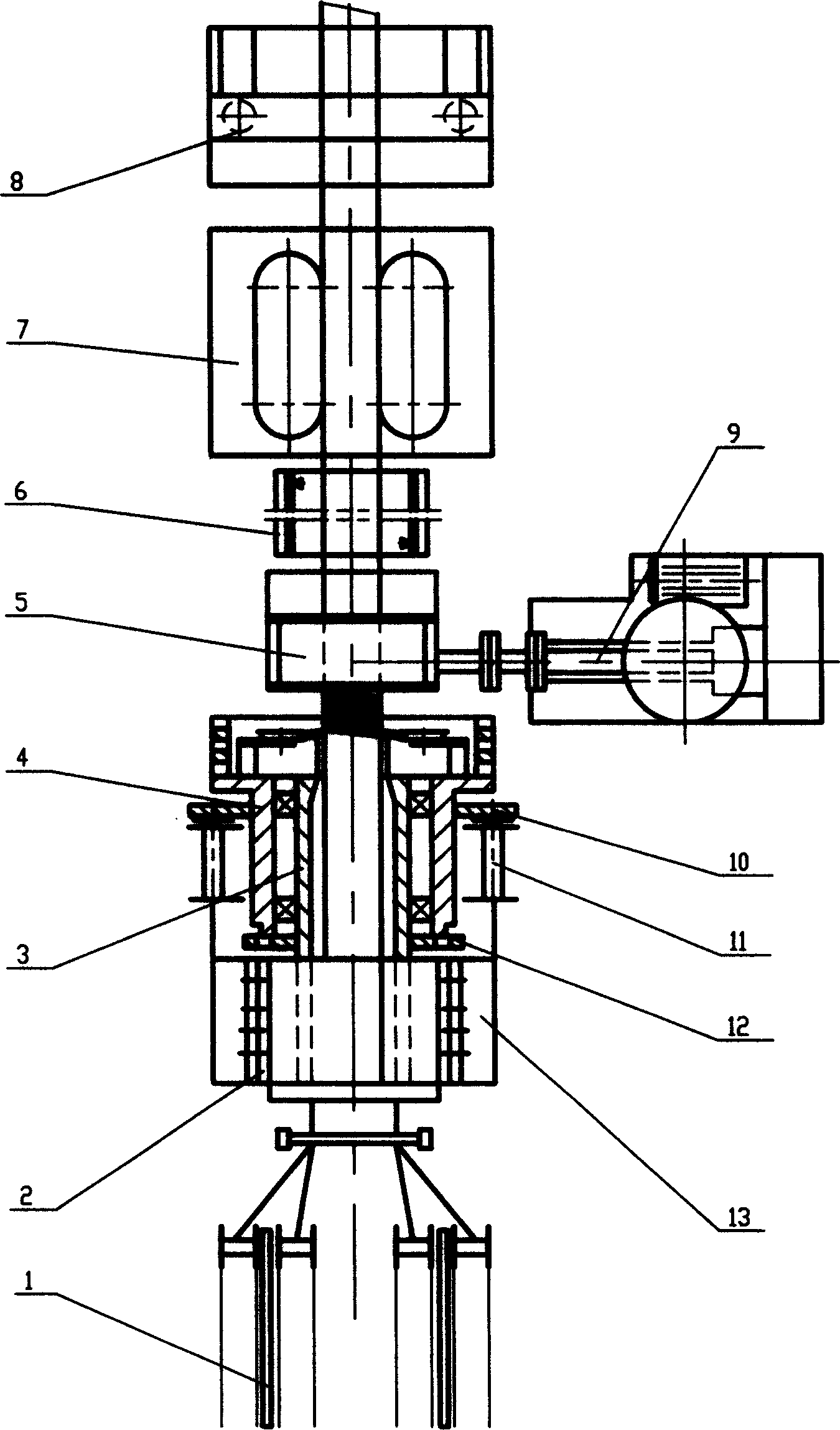
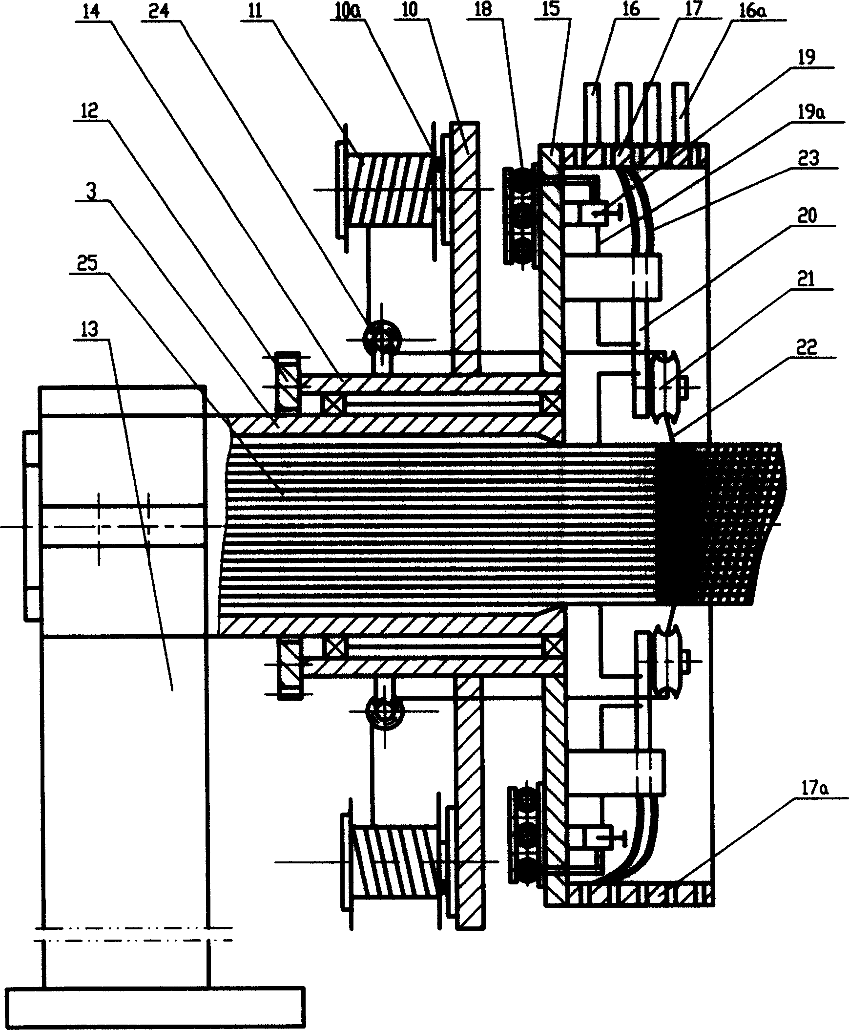
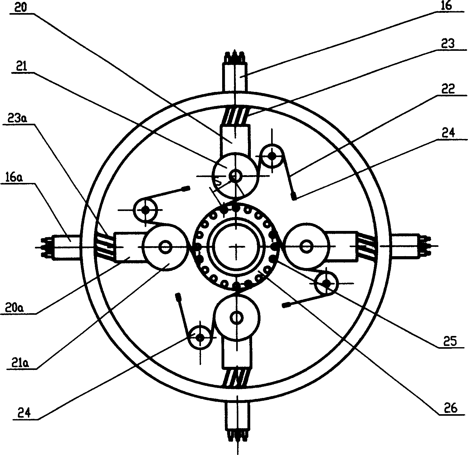
[0024] see figure 1 and 2 , the warp steel wires uniformly distributed along the circumferential axis are sent from the warp distribution device 1 through the warp channel to the welded mesh forming machine 2, and are connected to the traction head at the composite machine head 5. The welded mesh forming machine 2 is a cantilever structure, including a machine base 13, a cantilever support shaft 3 connected to the machine base 13, and a winding welding mechanism 4, wherein the machine base 13 and the cantilever support shaft 3 are fixed, and the winding welding mechanism 4 passes through the bearing Supported on the cantilever support shaft 3, the rotary winding function of the winding welding mechanism 4 is realized in this way: the motor drives the gear 12 meshed with the transmission mechanism through a conventional transmission mechanism (not shown), and the gear 12 is fixedly connected to the winding welding mechanism 4. on the connecting sleeve 14, so that the winding a...


PUM


Abstract

A composite steel skeleton-plastic pipe is prepared through welding the warp steel wires with the weft steel wires by net shaper and fuzzy resistance welding technology to form a netted steel skeleton, feeding it in a pipe shaping unit while extruding the fused plastics in it for combining the steel skeleton with the fused plastic, and cooling. Its making machine and the pipeline of said pipe are also disclosed.

Description

technical field [0001] The invention relates to a pipeline, especially a pipeline composed of a steel skeleton-plastic composite pipe, and also relates to a manufacturing method and device for the steel skeleton-plastic composite pipe. Background technique [0002] Pipelines generally include pipes and connecting structures. For example, the pipeline disclosed in WO9626380 has steel skeleton-plastic composite pipes and connecting structures. However, the excessively long steel frame and the exposed resistance wire setting of the connecting part of this technology cannot make the pipeline obtain a firm and reliable connection. [0003] Methods and devices for the manufacture of steel skeleton-plastic composite pipes are known. This technology is mainly embodied in SU1362645, WO94 / 09963, CN94104509, GB2277975 and other patents. [0004] Among them, SU1362645 is a step-by-step extrusion molding composite pipe technology. It first forms the inner plastic pipe, and there are wa...

Claims


Application Information

Patent Timeline
Patent Type & Authority Applications(China)
IPC IPC(8): B21F27/12B29CB29C45/14B29C48/09B29C48/13B29C48/153B29C48/21B29C48/32B29C65/34B29C70/68B29D23/00F16LF16L9/128F16L9/147F16L23/032F16L47/03
CPCB29C65/348B29C66/72141B29C66/1224B29C65/34B29C66/1226B29C66/116B29C66/7392B29C66/5221B29C66/1122B29C66/1312B29C65/344B29C65/342B29C66/7212B29K2105/206B21F27/124B29C47/023F16L9/128B29L2023/22B29C66/71B29C66/52295B29D23/003B29C66/5229B29C66/52241B29C66/5224B29C65/3468B29C66/52231B29D23/005B29C47/0023B29C66/5344B29C66/836B29C66/81811B29C48/09B29C48/13B29C48/153B29C48/21B29C66/1142B29C66/1162B29C66/73921B29K2023/06B29K2023/12B29K2305/12B29K2023/04B29K2023/10B29K2305/00B29K2023/065
Inventor 何轶良
Owner ハルビンスターウェイマシーナリーマニュファクチャリングカンパニーリミテッド
Why Eureka
Try Eureka