Over-inflation protecting apparatus

A technology of protection devices and components, applied in valve devices, valve operation/release devices, packaging, etc., can solve problems such as inability to accurately control filling volume, poor conversion accuracy, poor sealing effect, etc., and achieve simple structure and extreme conversion The effect of accurate position and long service life

A technology of protection devices and components, applied in valve devices, valve operation/release devices, packaging, etc., can solve problems such as inability to accurately control filling volume, poor conversion accuracy, poor sealing effect, etc., and achieve simple structure and extreme conversion The effect of accurate position and long service life

CN1566742AInactive Publication Date: 2005-01-19李平安 +1

Image

  • Over-inflation protecting apparatus
  • Over-inflation protecting apparatus
  • Over-inflation protecting apparatus

Examples


Embodiment Construction

[0054] Drawing No.:

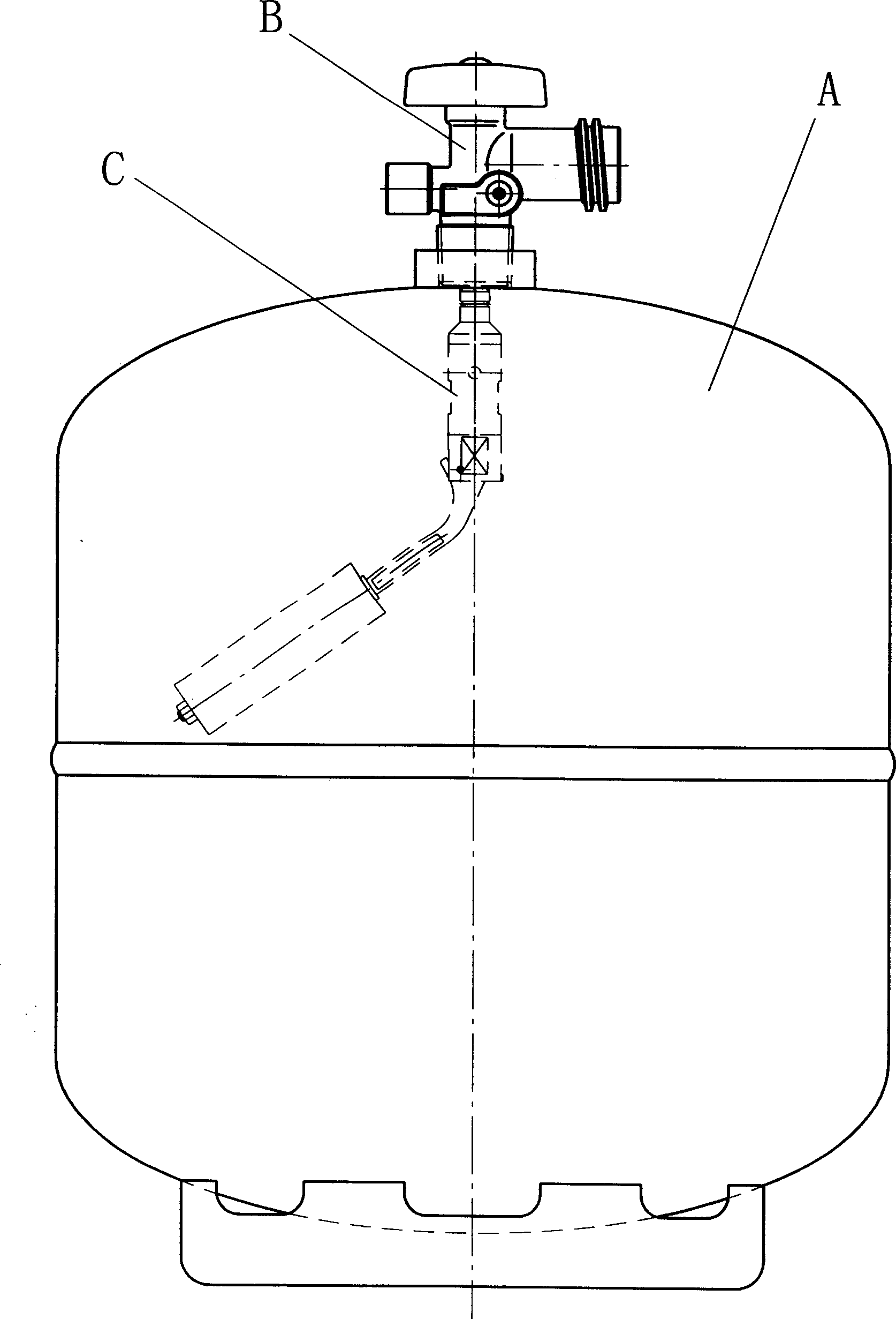
[0055] A. Steel cylinder B. Cylinder valve C. Overfill protection device

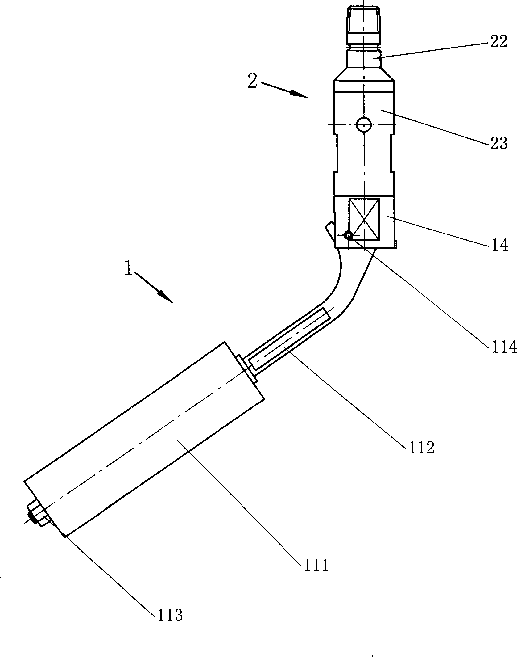
[0056] 1. State component

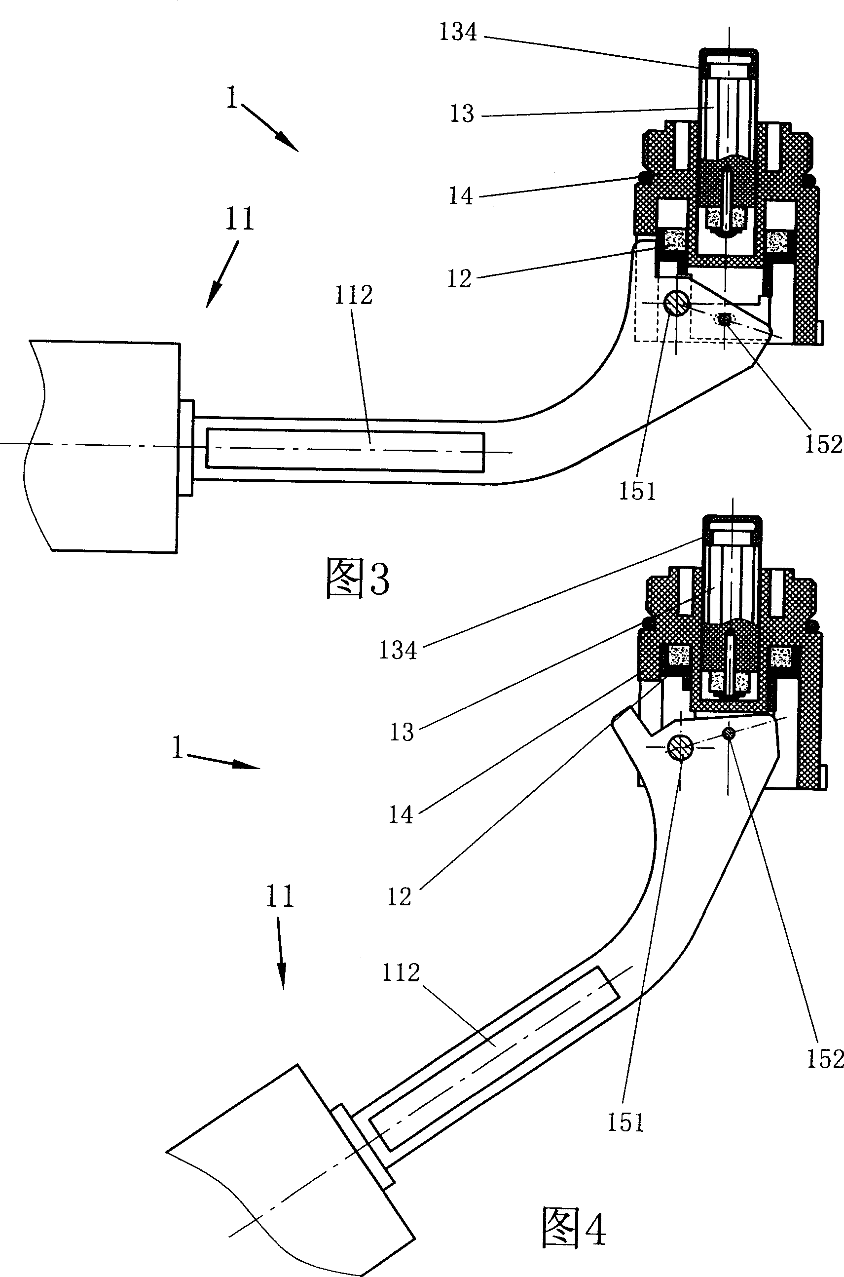
[0057] 11. Float parts

[0058] 111. Float 112. Connecting rod 113. Nut

[0059] 114. Large hole 115. Small hole

[0060] 116. Block

[0061] 12. Magnetic ring sleeve (component)

[0062] 121. Magnetic ring 122. Magnetic ring seat

[0063] 13. Spool (component)

[0064] 131. Screw 132. Magnetic 133. Spool stem

[0065] 134. Spool pad

[0066] 14. Lower part

[0067] 141. Lower end cover 142. O-ring 143. Round hole with bottom

[0068] 144. Ring groove

[0069] 151. Shaft 152. Pin shaft

[0070] 2. Opening and closing components

[0071] 21. Piston (component)

[0072] 211. Piston body 212. (Bowl-shaped) piston gasket 213. Y-shaped sealing ring

[0073] d1. Valve port hole

[0074] d2. Radial hole

[0075] 22. Upper end cap D1. Inlet hole

[0076] 23. Barrel

[0077] D2. Axial hole (inflow hole)

[0078] D3. (with top) valve hole (chan...


PUM


Abstract

An excess charging protector mounted in a liquified petroleum gas pot comprises a state assembly and an on-off assembly. The state assembly has a connecting rod with a float mounted thereon. The connecting rod is hinged with a lower end cover and connects a magnetic loop support. The magnetic loop support with a builtin magnetic loop is mounted in an annular recess of the lower end cover. A valve core rod is mounted in a closedended round meshed pipe of the lower end cover. A magnetic core is mounted at the bottom of the valve core rod. The magnetic core upper plane magnetic pole has identical polarity with that of the magnetic loop. The on-off assembly barrel has a valve port pore communicated with a radial pore. There are axial inflow pores around the valve port pore. A piston cushion on a piston body mounted in lower inner cavity of the valve port pore aligns said valve port pore. Inner bores of the piston body and the barrel are sealed sliding fit. The radial pore communicated with the barrel inner cavity is in inner cavity of the piston body. The barrel underpart is rigidly coupled to the lower end cover. The state assembly applies the two-magnetism repulsion principle to act, and the action can be completed at pole momentarily, and the pole location can be converted exactly. The on-off assembly utilizes the big and small pore flow velocity pressure gradient principle of fluid, and the action is quick and reliable. It is suitable for fine accurate control, and has a good sealing effect.

Description

technical field [0001] The present invention relates to a special protection device for LPG cylinders, which is installed in LPG cylinders. Background technique [0002] All bottles used to fill flammable and explosive liquids, such as "propylene, propane" and other liquefied gases, require that the filling liquid level must not exceed a certain height, and there must be enough space on the top of the bottle to ensure safety. Because this type of liquefied gas has a high coefficient of thermal expansion, the increase in the ambient temperature can cause the pressure of the bottle to increase rapidly. If there is not enough space, it will exceed the rated strength of the bottle and cause an accident. Therefore, this type of liquefied gas is required Proper space must be reserved for gas cylinders, and most of the rapidly increasing pressure is offset by compressing the space inside the cylinder, so the space at the top of the cylinder has a direct impact on the safety of the ...

Claims


Application Information

Patent Timeline
19 Jan 2005
Publication
CN1566742A
IPC
F16K31/18; F16K31/26; F16K31/56; F17C6/00; F17C13/02; F17C13/04
CPC
F17C2250/075; F16K31/56; F17C2221/035; F17C2223/033; F17C13/021; F17C2260/022; F17C13/04; F16K31/26
Inventors
李平安