Machine arrangement for dust-free chamber production program

A technology of clean room and program, applied in the direction of exposure device of photo-plate-making process, photo-plate-making process of pattern surface, identification device, etc., can solve the problems of waste of manufacturing time, simplicity, and reduction of product yield

Inactive Publication Date: 2005-01-19
AU OPTRONICS CORP
View PDF0 Cites 1 Cited by
  • Summary
  • Abstract
  • Description
  • Claims
  • Application Information

AI Technical Summary

Problems solved by technology

However, this configuration method usually does not take into account the smoothness of the production process. Therefore, in the manufacturing process, the substrate needs to be repeatedly transported to and from the far-distance machines, which wastes a lot of manufacturing time in the transport process, causing production problems. Reduced efficiency and increased costs
[0004] Furthermore, in the case of general machine operation or maintenance, there will be people walking on the AGV delivery aisle, so the risk of people being hit by the AGV increases. It will increase the probability of particles falling on the substrate and reduce the yield of products
[0005] In addition, in the photoresist removal process, the stripping machine can only provide a simple photoresist removal function, and there is no way to replace the cleaning machine in the production process.

Method used


Image

  • Machine arrangement for dust-free chamber production program
  • Machine arrangement for dust-free chamber production program
  • Machine arrangement for dust-free chamber production program

Examples


Embodiment 1

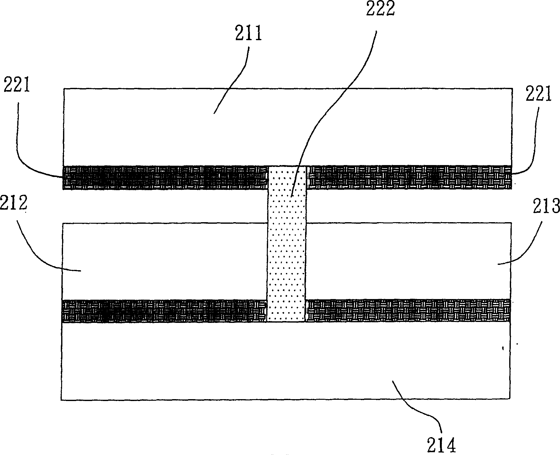
[0031] Please see first figure 2, which is a schematic diagram of machine configuration in Embodiment 1 of the present invention. In this embodiment, the machines with the same type of production process are mainly placed in the same row, and the processing substrate is transported by the robot arm or OHS of the storage cabinet. As can be seen in the figure, it is mainly divided into four types of machines, namely a photolithography machine 211, an etching and photoresist removal machine 212, and a thin film deposition machine 213, which are separated from each other by a storage cabinet, and AGV is not used at all, so AGV aisle is not needed, which greatly increases the utilization efficiency of space configuration. The substrate handling between the machines is performed by the robotic arm of the storage cabinet 221, or carried by the OHS 222, which further reduces the chance of particles falling on the substrate due to the approach of personnel or the movement of the AGV,...

Embodiment 2

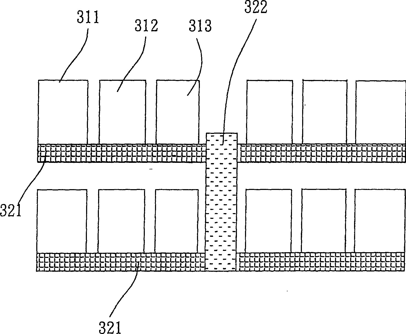
[0033] See image 3 , which is a schematic diagram of machine configuration in Embodiment 2 of the present invention. In this embodiment, the production process machines of the same layer, such as thin film deposition 311, lithography 312, and etching removal 313, etc., are placed on the moving line of the same storage cabinet 321. The advantage is that the connected storage cabinets And exempt the AGV from being exposed to the air when loading and unloading, causing the particles to fall on the substrate. On the other hand, this embodiment can also eliminate the space occupied by the AGV walkway, reduce equipment space costs, and at the same time prevent people from being hit by the AGV. At the same time, transported by the storage cabinet 321 or OHS322, personnel do not need to go to the front of the machine to operate, and also reduce the particles brought by personnel walking. In addition, placing the production process machines on the same layer on the same production p...

Embodiment 3

[0035] Please refer to FIG. 4 , which is a schematic diagram of an integrated machine according to Embodiment 3 of the present invention. As mentioned above, in order to improve the productivity of each machine, the integrated machine 412 proposed in this embodiment can integrate the production procedures such as etching, photoresist removal, surface treatment and cleaning into the same machine. To improve the productivity of this machine, on the other hand, it also reduces the redundant machine space and lowers the equipment cost. The front of the integrated machine 412 is connected with a photolithography machine 411, followed by a thin film deposition machine 413, and each machine is connected to a storage cabinet 421, and a glass substrate added by a robotic arm 422 Into the import port 423 of the storage cabinet 421.


PUM


Abstract

This invention is about a kind of producing procedure machine configuration of clean room. It assorts with at least one baseboard. It comprises: several exposure machines, which used for exposure producing procedure to the base board; several aggradation machines, which used for aggradation producing procedure to the base board; several etching cleaning integration machines, each of them is located between the exposure machine and aggradation machine, and used for etching, cleaning producing procedure to the base board; as well as OHS apparatus, which spans the exposure machine, aggradation machine and etching cleaning integration machine and on the top of them, and used for transportation the base board from the exposure machine, aggradation machine to the etching cleaning integration machine.

Description

technical field [0001] The invention relates to a machine configuration method for a clean room, in particular to a clean room manufacturing procedure machine configuration suitable for the flat panel display industry. Background technique [0002] In the related industries of semiconductor or flat panel display, a substrate used to manufacture semiconductor elements or displays typically undergoes manufacturing procedures such as lithography, etching, photoresist removal, surface treatment, cleaning, deposition, etc., and each manufacturing procedure They are respectively carried out in an independent production program machine. Generally speaking, each production process machine such as etching machine 111, photoresist stripping machine 112, cleaning machine 113 and film forming machine currently exists in an independent form, and will occupy a large area of ​​the clean room. space, such as figure 1 shown. This configuration, for an industrial factory area with limited ...

Claims


Application Information

Patent Timeline
Patent Type & Authority Applications(China)
IPC IPC(8): B08B11/00G03F7/00G03F7/20G03F7/26G09F9/00
Inventor 林奇锋
Owner AU OPTRONICS CORP
Why Eureka
Try Eureka