A current regulator for charging and discharging of superconducting magnet

A technology of current regulator and superconducting magnet, which is applied in the direction of conversion equipment with intermediate conversion to AC, and can solve the problems of large switching loss, increased magnet AC loss, and large magnet excitation voltage.

Inactive Publication Date: 2005-01-19
INST OF ELECTRICAL ENG CHINESE ACAD OF SCI
View PDF3 Cites 14 Cited by
  • Summary
  • Abstract
  • Description
  • Claims
  • Application Information

AI Technical Summary

Problems solved by technology

The problem is that not only two sets of equipment are needed for charging and discharging, but also the capacity of the charging equipment is very large if it is necessary to keep the magnet current constant and to complete the fast charging function, such as US Patent 6,157,094 "Superconducting magnet and its power supply device"; , figure 1 US2002 / 0030952 "Superconducting Magnet Discharge Method and Device" shown in the specific structure diagram, 10 and 11 are the magnet part, 19 is the magnet charging power supply, and other parts are the discharge part, that is, the chopper, which will replace the superconducting magnet. Convert current directly to voltage
It cuts the magnet current directly by the switches 22 and 20, which makes the switching loss very large, and the capacitor capacity required by the DC voltage 25 is very large, so that the excitation voltage of the magnet is large, which is not only unfavorable for the stability of the magnet, but also makes Magnet AC loss increases, increasing the operating cost of the magnet

Method used


Image

  • A current regulator for charging and discharging of superconducting magnet
  • A current regulator for charging and discharging of superconducting magnet
  • A current regulator for charging and discharging of superconducting magnet

Examples


Embodiment Construction

[0014] The present invention will be further described below in conjunction with accompanying drawing and embodiment:

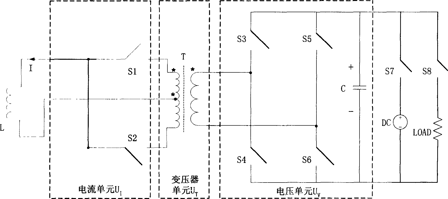
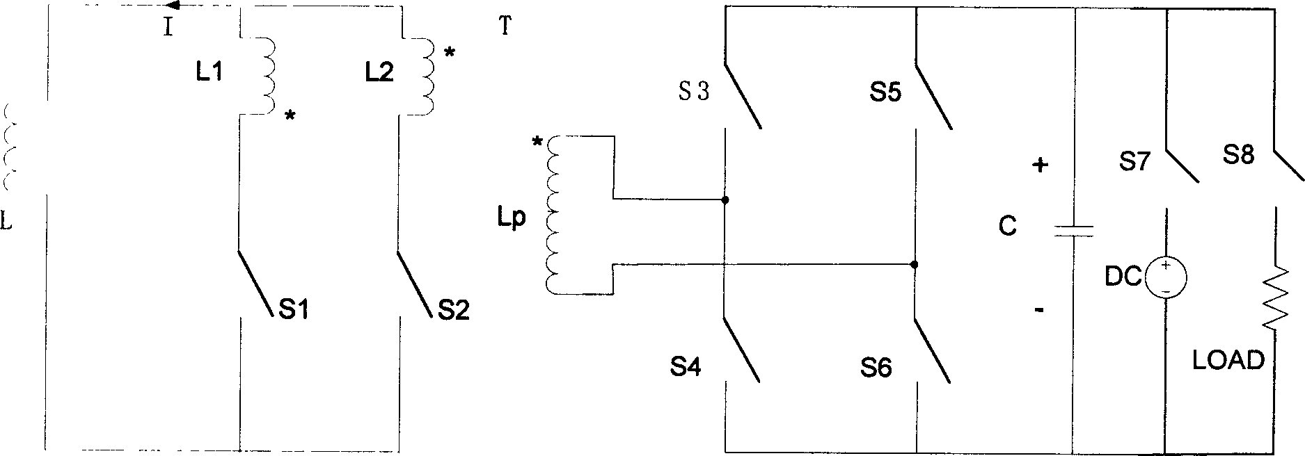
[0015] The main circuit circuit diagram of the present invention is as figure 2 as shown, image 3 It is a schematic diagram of the main circuit of the present invention.

[0016] figure 2 In the present invention, the voltage unit U I , Transformer unit U T , with the current unit U V It consists of three parts. Transformer unit U T It is a transformer with taps on one side connected to the current unit. Voltage unit U V It is composed of a capacitor C on the DC side and two bridge arms of the voltage source converter composed of switches S3 and S4, S5 and S6 in series, respectively. The midpoint of the two bridge arms is the voltage source converter The AC output of is connected to the primary side of the transformer T. Current unit U I It is a current source converter, one end of its DC side is connected to the center tap of the transformer T,...


PUM


Abstract

The invention is a current regulator used in charging and discharging superconductive magnet, composed of a voltage unit, a transformer unit and a current unit, where the voltage unit is a voltage source converter whose DC side is a capacitor, the current unit is a current source converter with a DC side connected with a superconductive magnet, an AC output side of the voltage source converter is connected with a primary side of the transformer and that of the current source converter is connected with a secondary side of the transformer, and the transformer unit can be an ordinary transformer and also a transformer tapped on one side or both two sides. The invention can not only charge the magnet but release the electric energy stored in the magnet, and the charge and discharge voltage can be flexibly regulated. Its structure is compact and simple, its power density is high, and its bulk is small, and thus not only improves the property of the magnet charge-discharge system but can largely reduce the cost.

Description

Technical field: [0001] The invention relates to a current regulator used for charging and discharging a superconducting magnet, which belongs to the technical field of electric engineering. Background technique: [0002] Superconducting has the characteristics of zero resistance and high current-carrying capacity under a strong magnetic field, making superconducting magnets widely used, especially for large magnets used to generate strong magnetic fields in high-energy physics experiments, which have almost replaced all large-scale magnets. , conventional magnets that consume a lot of power; at the same time, with the development of superconducting power technology, especially micro-superconducting energy storage, it has been commercialized abroad and is widely used to improve power quality and power system stability. Superconducting magnets have been used like never before. [0003] The general operating current of superconducting magnets is at the kA level, and has a lar...

Claims


Application Information

Patent Timeline
Patent Type & Authority Applications(China)
IPC IPC(8): H02M3/28
Inventor 赵彩宏王晓刚肖立业林良真
Owner INST OF ELECTRICAL ENG CHINESE ACAD OF SCI
Why Eureka
Try Eureka