Potentionmetric DNA microarray, Process for producing same and method of analyzig nucleuic acid
一种电位滴定、解析方法的技术,应用在重组DNA技术、核苷酸文库、化学仪器和方法等方向,能够解决检测精度劣化、电极腐蚀、损害电流测定稳定性等问题
- Summary
- Abstract
- Description
- Claims
- Application Information
AI Technical Summary
Problems solved by technology
Method used
Image
Examples
Embodiment 1
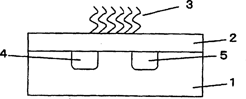
[0036] figure 1 It is a schematic cross-sectional view illustrating an example of the field effect transistor for gene detection of the present invention.
[0037] It is a structure in which a nucleic acid probe is immobilized on the surface of the gate insulator 2 of the insulated gate electric field effect transistor 1 . Nucleic acid probes use oligonucleotides or cDNA or fragments of DNA branched in the middle, usually consisting of less than or equal to 300 bases, which can hybridize with the target gene that should be determined under appropriate reaction conditions. In the case of nucleotides, nucleic acid fragments less than or equal to 80 bases in length are desired. Gate insulators, either alone or in combination with silicon dioxide (SiO 2 ), silicon nitride (SiN), aluminum oxide (Al 2 o 3 ), tantalum pentoxide (Ta 2 o 5 ) and other materials, usually, in order to keep the transistor working well, in silicon dioxide (SiO 2 ) on which a stack of silicon nitride...
Embodiment 2
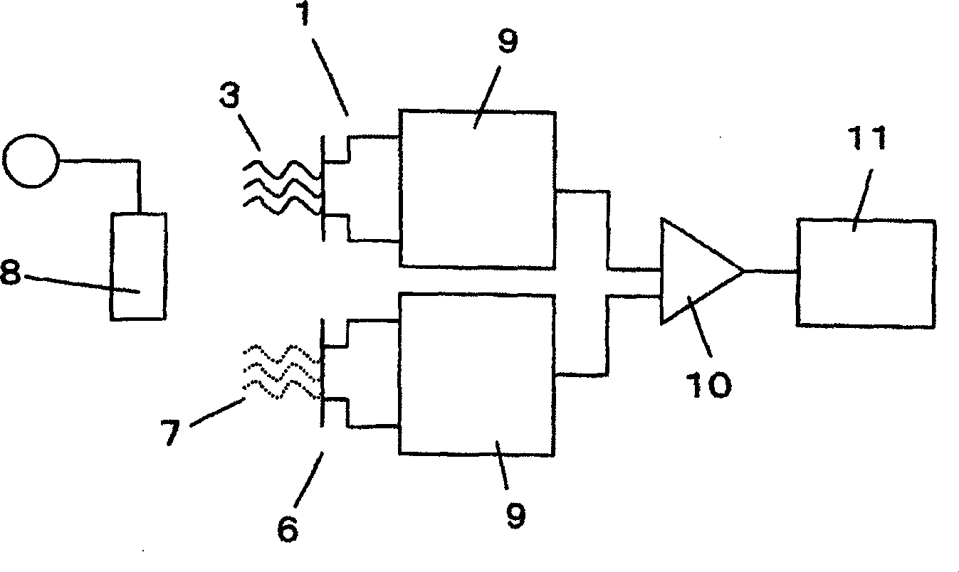
[0042] figure 2 is to use figure 1 It is a diagram showing a configuration example of a genetic testing system using an electric field effect transistor (Genetic FET) for genetic testing.
[0043] The genetic screening system, in addition to figure 1 In addition to the shown FET1 for gene detection, a reference FET6 is used to perform differential measurement between the FET for gene detection and the reference FET. A nucleic acid probe 3 having a base sequence complementary to the target gene in the sample is immobilized on the surface of the gate insulator of the FET 1 for gene detection. On the other hand, the nucleic acid probe 7 having a base sequence different from that complementary to the target gene is immobilized on the surface of the gate insulator of the reference FET6.
[0044] By performing such a differential measurement, the change in the output value due to the change in the ambient temperature or light caused by the difference in the electrical characteri...
Embodiment 3
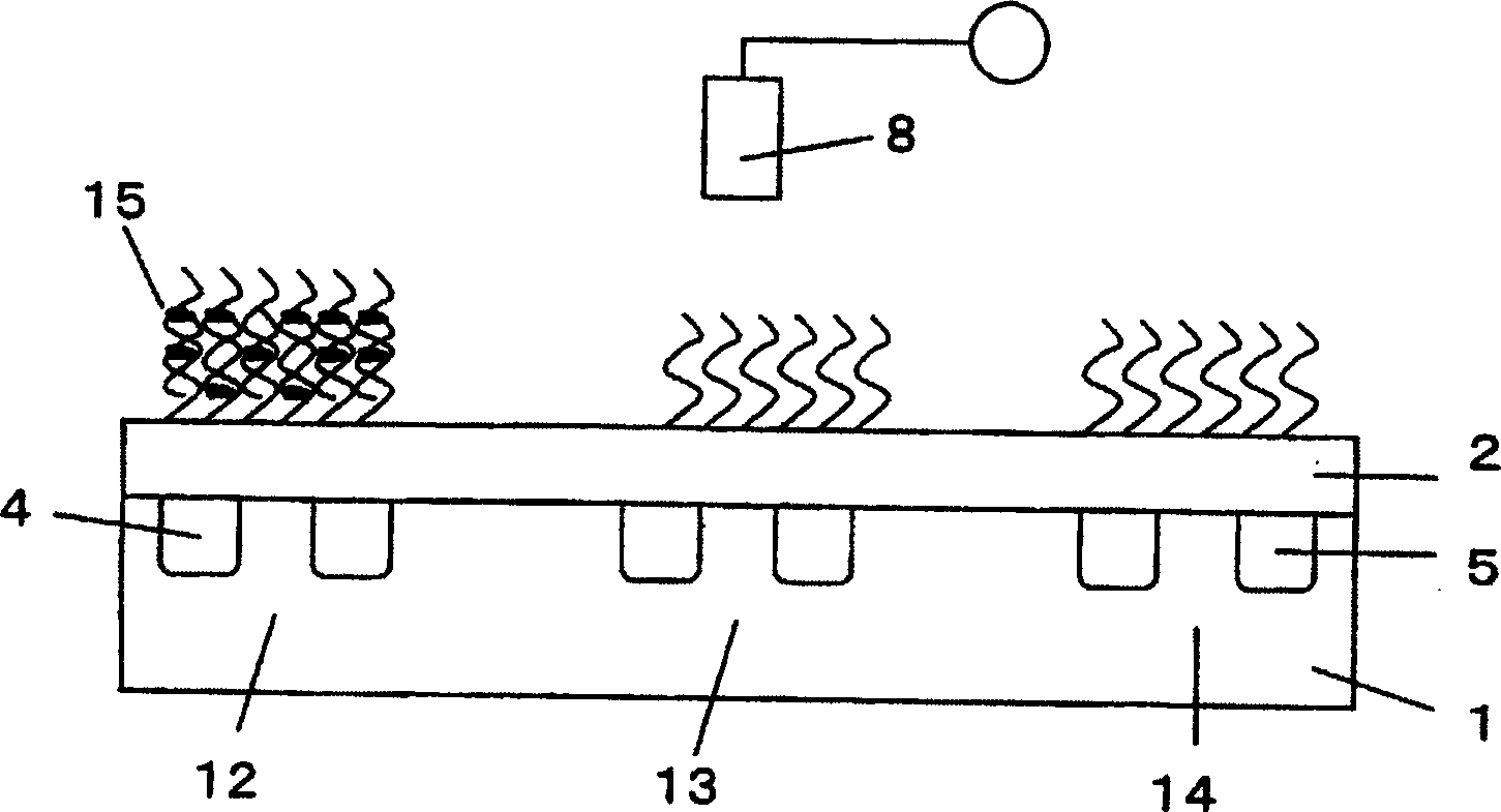
[0047] image 3 It is an explanatory diagram of a measurement system combining the DNA microarray and intercalator of the present invention. In the case of the DNA microarray shown in the figure, three Genetic FETs 12 to 14 are integrated, the first FET 12 is used as a gene detection FET for detecting the first target gene, and the second FET 13 is used as a gene detection FET for detecting the second gene FETs are used, and the third FET14 is used as a reference FET. Nucleic acid probes having base sequences complementary to the first and second genes are respectively immobilized on the gate insulators of the first and second FETs. A nucleic acid probe having a base sequence different from the complementary base sequences of the first and second genes is immobilized on the surface of the insulator of the reference FET.
[0048] image 3 It shows the state when a sample solution containing only the first gene is introduced into the above-mentioned integrated DNA microarray,...
PUM
 Abstract
Description
Claims
Application Information
 - R&D
- Intellectual Property
- Life Sciences
- Materials
- Tech Scout
- Unparalleled Data Quality
- Higher Quality Content
- 60% Fewer Hallucinations
Browse by: Latest US Patents, China's latest patents, Technical Efficacy Thesaurus, Application Domain, Technology Topic, Popular Technical Reports.
© 2025 PatSnap. All rights reserved.Legal|Privacy policy|Modern Slavery Act Transparency Statement|Sitemap|About US| Contact US: help@patsnap.com


