Snake type fiber-optical sensor burying and detecting method and its snake type fibre-optical sensor

An optical fiber sensor, serpentine technology, used in instruments, measuring devices, scientific instruments, etc., can solve problems such as large deformation and low strength, and achieve high accuracy, high precision, and stable testing.

Inactive Publication Date: 2005-03-02
CCCC TUNNEL ENG +1
View PDF0 Cites 21 Cited by
  • Summary
  • Abstract
  • Description
  • Claims
  • Application Information

AI Technical Summary

Problems solved by technology

However, there are currently a large number of geotechnical projects with low strength and large deformation, such as urban subway projects, high-rise building foundations, deep foundation pits, extremely thick loose...

Method used


Image

  • Snake type fiber-optical sensor burying and detecting method and its snake type fibre-optical sensor
  • Snake type fiber-optical sensor burying and detecting method and its snake type fibre-optical sensor
  • Snake type fiber-optical sensor burying and detecting method and its snake type fibre-optical sensor

Examples


Embodiment 1

[0078] 1.2×0.12m plane stress model experiment

[0079] Figure 11 It is a 1.2×0.12m plane stress model experiment rack with optical fiber sensor layout and test system. The experimental materials are ordinary river sand, gypsum, large white powder and mica powder, and the simulation of various rock formations is realized through the ratio design. The pavement height of the model is 50cm, the geometric similarity ratio is 100, the bulk density ratio is 1.7, and the thickness of the mining coal seam is 3.5cm. Embed optical fiber sensors in three layers, the No. 3 optical fiber is buried in the mudstone of the model, which is 40.5cm away from the coal seam floor; the No. 2 optical fiber is buried in the siltstone, 24cm from the coal seam floor; the No. 1 optical fiber is buried in the fine sandstone Middle, 7cm from the bottom of the coal seam. The optical fiber length of the test system is 2.178km, and optical fiber 1 is connected to the OTDR optical time domain reflectomete...

Embodiment 2

[0084]2m model rock beam experiment

[0085] Figure 13 It is the experimental situation of the 2m model. The height of the model is 11.5cm, the layer thickness is 1cm, and the coal seam thickness is 3.5cm. Two layers of optical fibers are buried in the rock beams. The No. 1 optical fiber is buried at a distance of 5 cm from the coal seam floor, and the No. 2 optical fiber is buried at a distance of 8 cm from the coal pillar and coal seam floor. The optical fiber 1 test system is connected in series. Each optical fiber sensor is connected in series through an optical fiber 1. One end of the optical fiber 1 is connected to an OTDR optical time domain reflectometer. Since the spatial resolution of the time domain meter used in the experiment is in the range of decimeters, in order to Accurate positioning, access transition optical fiber and pigtail between optical fiber sensors. A dial indicator is installed in the middle of the rock beam.

[0086] The coal seam under the ro...


PUM

PropertyMeasurementUnit
Lengthaaaaaaaaaa
Diameteraaaaaaaaaa

Abstract

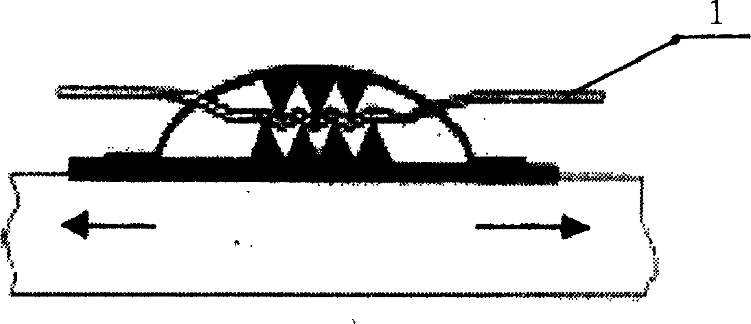
The invention relates to the imbedding and test method for a snake optical fiber sensor and the snake optical fiber sensor. The method involves making and imbedding the optical fiber sensor, connecting the optical fiber sensor to a transition optical fiber with a bonding machine to position the the optical fiber sensor, testing the loss initial value, after excavating, test system loss changing curve of the optical fiber test system and observing the deformation and damage condition of the terrain; processing the OTDR test data with program. The bare fiber is covered with a bushing on the outside diameter and equipped with a protecting device on both end. The fiber can form many minor bend point used to monitor the deformation of rock whose strength is lower than quartz glass and the generating, developing, microdeformation and macrodeformation of the cranny of large deformed rocks. The initial deformation of the terrain, even the damage of materials,can be detected with the accuracy within plus or minus 0.01mm. The marodeformation reaches 35-50 mm, far higher than the concrete deformation detection. It is a distributed optical fiber detecting instrument, the fiber is connected with the detecting device, convenient to operating, detection is stable, highly accurate.

Description

technical field [0001] The invention relates to an embedding and testing method of an optical fiber sensor and the optical fiber sensor thereof, and is particularly suitable for the embedding and testing method of the serpentine optical fiber sensor and the serpentine optical fiber sensor for structure monitoring with low strength and large deformation. Background technique [0002] In recent years, some technologically advanced countries are researching a novel method for condition monitoring and damage estimation of composite materials—fiber-optic sensitive materials and structures, embedding optical-fiber sensing systems into building structures to form intelligent building materials, that is, the key to materials and structures. The optical fiber sensor is embedded in the position to detect the internal stress and strain changes during use and operation, and to monitor the deformation, cracks, delamination and other damages caused by external loads and material fatigue in...

Claims


Application Information

Patent Timeline
IPC IPC(8): G01N21/84G01N35/00G02B6/24G02B6/255
Inventor 柴敬
Owner CCCC TUNNEL ENG
Why Eureka
Try Eureka