Light burst exchange network edge node structure and realizing method

A technology of optical burst switching and network edge, which is applied in the direction of data switching network, electromagnetic wave transmission system, digital transmission system, etc. It can solve the problems of increasing optical network delay, increasing overhead and delay, and deteriorating network throughput performance.

Inactive Publication Date: 2005-03-02
SHANGHAI JIAO TONG UNIV
View PDF0 Cites 5 Cited by
  • Summary
  • Abstract
  • Description
  • Claims
  • Application Information

AI Technical Summary

Problems solved by technology

[0003] Found through the retrieval of prior art literature, edge node structure (Yi jun Xiong, Marc Vandenhoute, and Hakki C.Cankaya.Control Architecture in Optical Burst-Switched WDMNetworks, IEEE Journal on Selected Areas in Communications , 2000, 18(10): 1838-1850) continues to use the traditional circuit switching traffic mode, still adopts the assembly method of fixed packet length and time, and assembles and offset time bring additional delay, which cannot meet the requirements of burstiness and self-similarity of the data network; the existing edge node structure does not involve the fairness of distinguishing services, and different types of services in the network have different delay requirements, and high priority High-level services must guarantee a small delay, while low-priority services can tolerate relatively large delays, and it is meaningless to guarantee QoS withou

Method used


Image

  • Light burst exchange network edge node structure and realizing method
  • Light burst exchange network edge node structure and realizing method
  • Light burst exchange network edge node structure and realizing method

Examples


Embodiment Construction

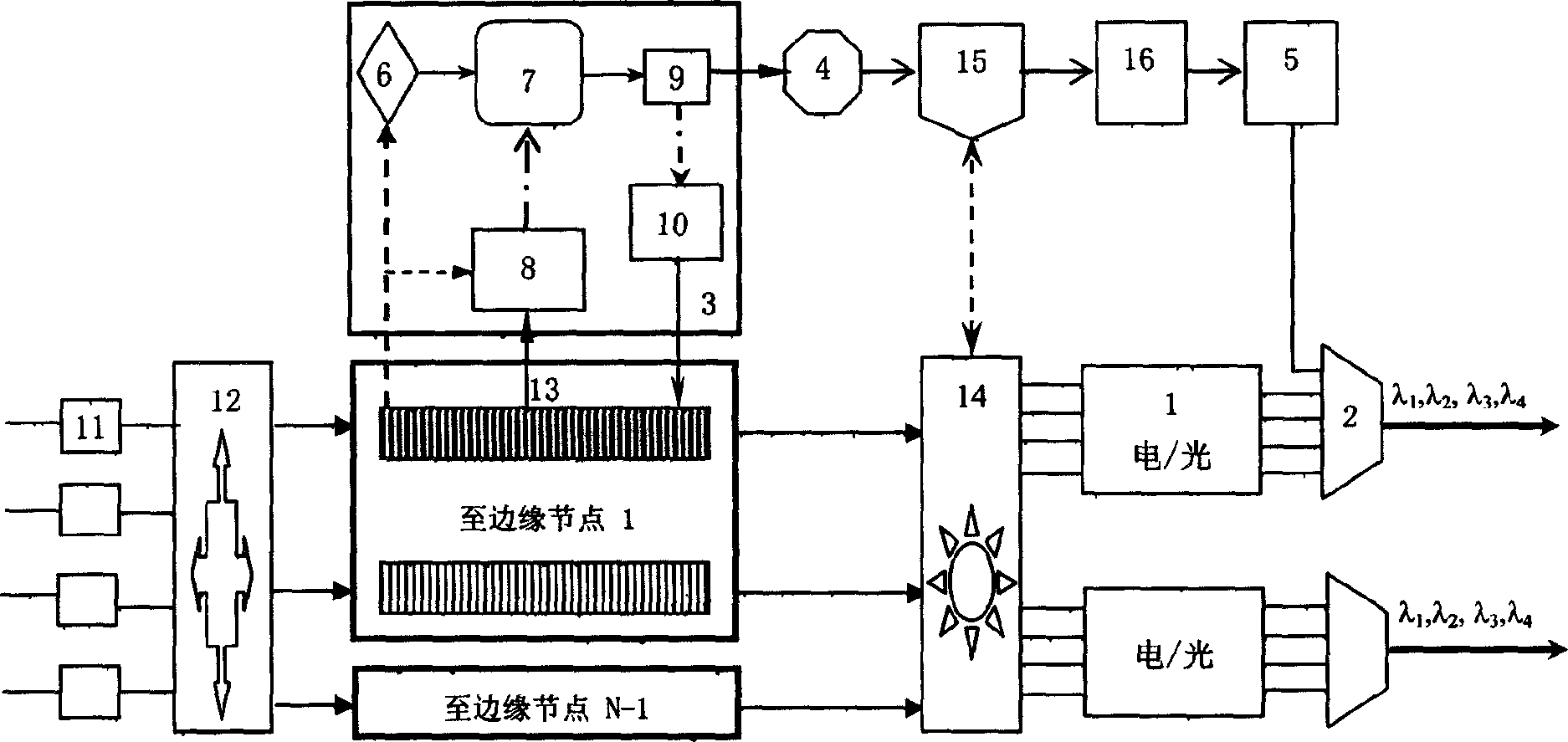
[0040] Such as figure 1 As shown, the edge router node structure of the present invention includes: an optical packet transmitting module 1, a wavelength division multiplexer 2, an adaptive flow assembly module 3, a bias determination module 4, and a control packet transmitting module 5, and its connection relationship is: adaptive The traffic assembly module 3 is connected to the bias determination module 4 and then connected to the control packet transmission module 5, the optical packet transmission module 1 and the control packet transmission module 5 are connected to the wavelength division multiplexer 2 for transmission, and the adaptive traffic assembly module 3 includes control Packet trigger module 6, AAR(p) filter 7, l(n-I) and e(n) memory 8, packet length determination module 9, dynamic BAT decision module 10, control packet trigger module 6 output connected to AAR(p) filter 7, l (n-1) and e (n) memory 8 outputs are also connected to AAR (p) filter 7 as input, and t...


PUM


Abstract

A light burst exchange network edge nodal structure includes a control packet, a light packet emit module, a WDM, an adaptive flow assembly module and a bias determining module, among which, the adaptive module is connected with the bias determining module then to join in the control packet emit module to be connected in the WDM to be transferred together with the light packet emit module, a control packet trigger module in the adaptive flow assemble module is connected into AAR(P) filter, I(n-1) and e(n) memory are also connected into the AAR(P) filter as the input, the output of AAR(p) is connected with a packet length determine module, output of which is linked to dynamic BAT decisive module.

Description

technical field [0001] The invention relates to a network structure and an implementation method used in the technical field of optical communication, in particular to an optical burst switching edge node structure and an implementation method based on dynamic self-adaptive assembly of real-time network services. Background technique [0002] The optical burst switching (OBS) network reduces the requirements for optical switches and optical buffers, can well support bursty packet services, and realizes large packet switching and transparent transmission under current optical technology conditions, and has become one of the hotspots in the field of optical communication research. one. It consists of several edge nodes and core nodes. The edge node is responsible for completing the interface with the traditional network. The ingress edge node assembles traditional electronic packets into bursts according to the requirements of the destination address and quality of service (Qo...

Claims


Application Information

Patent Timeline
IPC IPC(8): H04J14/02H04L12/24H04L12/701H04L12/801
Inventor 隋志成曾庆济肖石林
Owner SHANGHAI JIAO TONG UNIV
Why Eureka
Try Eureka