Blaze insulating fluidized forge furnace

A calciner and fluidized technology, applied in the field of flame-chambered fluidized calciner, can solve the problems of lower effective utilization rate of heat, high heating temperature of surrounding materials, poor flame stability, etc., to increase heating time and overcome calcined materials Effect of overburning and improving heat utilization rate

Inactive Publication Date: 2005-06-29
INST OF PROCESS ENG CHINESE ACAD OF SCI
View PDF0 Cites 15 Cited by
  • Summary
  • Abstract
  • Description
  • Claims
  • Application Information

AI Technical Summary

Problems solved by technology

For the calcination of powder materials, the fluidized bed calciner has fast heat transfer and mass transfer, low energy consumption, and large production capacity of a single equipment, but the existing fluidized bed calciner heating method is directly heated inside the furnace or a combustion chamber is set outside. , which leads to the following problems: First, the fuel burns in the furnace, the flame is in direct contact

Method used


Image

  • Blaze insulating fluidized forge furnace

Examples


Embodiment Construction

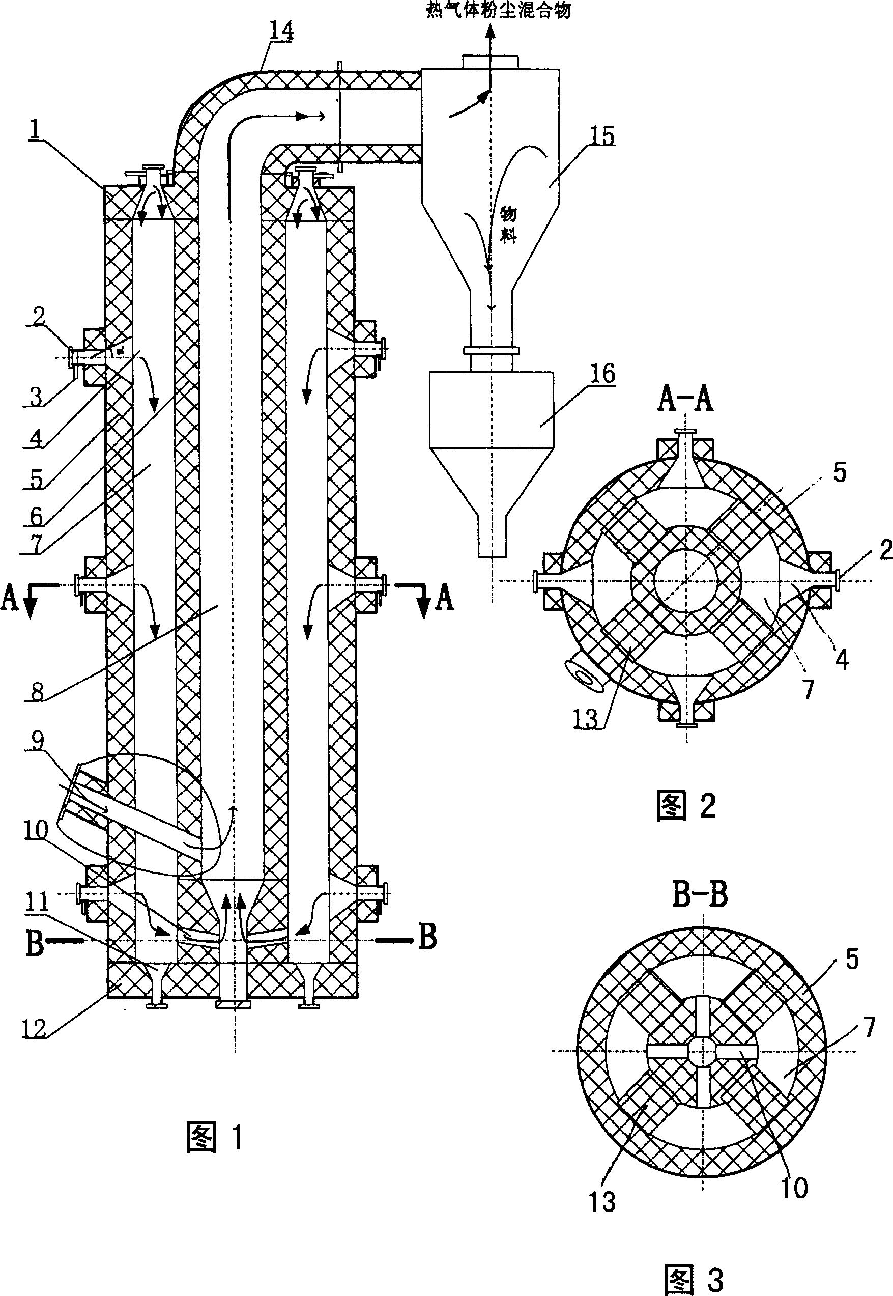
[0024] As shown in Fig. 1, Fig. 2 and Fig. 3, it is a structure diagram of a flame-chambered fluidized calciner of the present invention. Flame fluidized calciner includes furnace roof 1, burner burner 2, secondary combustion air pipe 3, combustion chamber 4, furnace outer wall 5, furnace wall 6, flue 7, furnace 8, feed pipe 9, Channel 10, soot cleaning hole 11, furnace bottom cover 12, flame partition wall 13, outlet connecting pipe 14, high temperature gas-solid separator 15, cooling unloader 16.

[0025] Wherein, the outer wall 5 of the furnace is a hollow cylinder, and a plurality of burner burners 2 and feeding pipes 9 are arranged on the side peripheral surface thereof. The burner burners 2 are evenly arranged on a plurality of equal-height circles that are vertically evenly distributed. The inner end of the burner 2 of each burner communicates with the combustion chamber 4, and the two correspond one by one. Referring to the sectional view A-A in FIG. The combustion c...


PUM


Abstract

The invention is about the fire stove, which concerns fire equipment technique field. The invention makes use of firing heat the stove indirectly, avoiding the direct contact of fire and material, so it overcome the material over fire phenomenon, at the same time, the smoke go to the stove up to down, increasing the heat time for a time. Compared with the fire material directly, it increases the heat effect by much time. The material in the invention can stop for some seconds to hours, the temperature of the stove is 500-1300 degC, the difference in temperature is between minus 5 and plus 5 degC. The invention transfers the heat fast, the temperature in the stove is even, and it uses low energy.

Description

technical field [0001] The invention relates to a flame-insulated fluidized calciner, which relates to the technical field of calcining equipment. Background technique [0002] At present, calcining equipment includes fluidized bed calcining furnace, rotary kiln, multi-layer furnace, tunnel kiln and so on. For the calcination of powder materials, the fluidized bed calciner has fast material heat transfer and mass transfer, low energy consumption, and large production capacity of a single equipment, but the existing fluidized bed calciner heating method is directly heated inside the furnace or a combustion chamber is set outside. , which leads to the following problems: First, the fuel burns in the furnace, the flame is in direct contact with the material, the flame stability is poor in the dense phase, and the local temperature in the furnace is too high, which makes the surrounding material heated to a high temperature, resulting in overburning of the material; in addition,...

Claims


Application Information

Patent Timeline
IPC IPC(8): B21J17/00
Inventor 卢旭晨
Owner INST OF PROCESS ENG CHINESE ACAD OF SCI
Why Eureka
Try Eureka