Method for manufacturing optical fiber unsensitive to hydrogen

A manufacturing method and sensitive technology, applied in the field of optical fiber manufacturing, can solve the problems of complex production process, increased production process, long processing time, etc., to achieve the effect of improving processing effect, reducing subsequent processing steps, and improving production efficiency

Active Publication Date: 2005-06-29
YANGTZE OPTICAL FIBRE & CABLE CO LTD
View PDF2 Cites 8 Cited by
  • Summary
  • Abstract
  • Description
  • Claims
  • Application Information

AI Technical Summary

Problems solved by technology

These methods all belong to off-line processing methods, require special reaction vessels and equipment, have a long processing time, and increase the production process, making the production process complicated

Method used


Image

  • Method for manufacturing optical fiber unsensitive to hydrogen
  • Method for manufacturing optical fiber unsensitive to hydrogen
  • Method for manufacturing optical fiber unsensitive to hydrogen

Examples


Embodiment 1

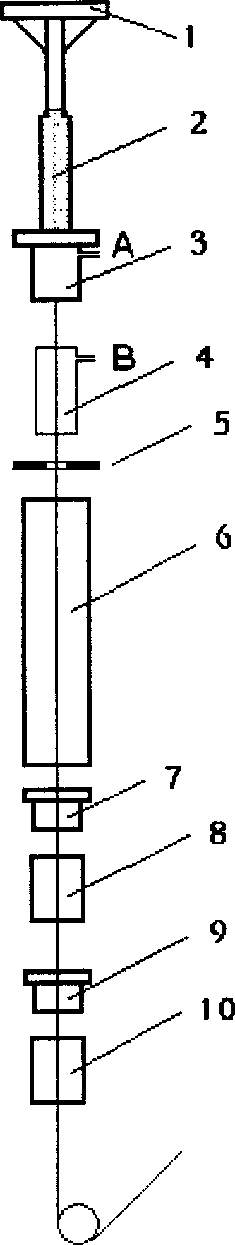
[0024] Manufacturing method and main device of the present invention such as figure 1 As shown, the drawing device includes a wire drawing furnace 3, and a preform rod 2 with a diameter of 80 mm is fed into the wire drawing furnace 3 at a certain rate under the action of the feeding mechanism 1, and the preform rod 2 is heated to 2000 °C in the wire drawing furnace 3. ℃, the bare optical fiber is drawn from the softened bottom of the preform, and its outer diameter is measured by the outer diameter measuring device 5 after passing through the holding furnace 4. The diameter of the bare optical fiber is generally 125 μm. The bare optical fiber enters the coater after passing through the cooling pipe 6, and resin is coated around the optical fiber to protect the optical fiber from damage. The resin coating is made of UV curable resin and cured by a UV curing furnace. After being cured by the inner coating applicator 7 and the curing furnace 8 and the outer coating applicator 9 a...

Embodiment 2

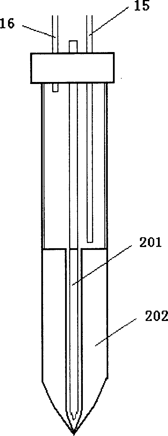
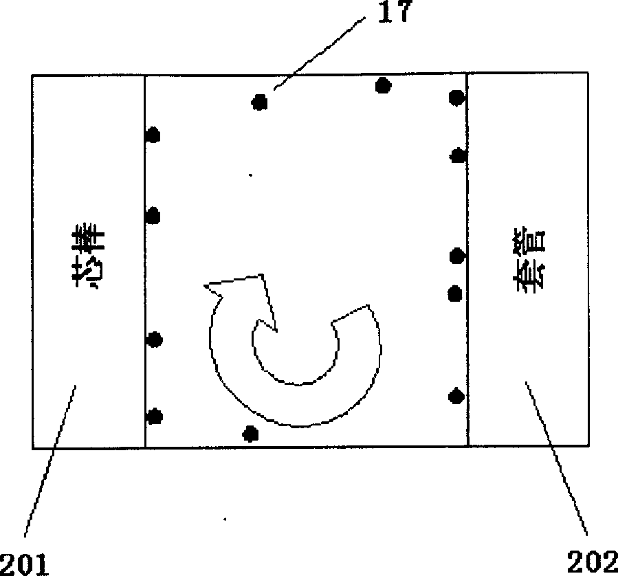
[0031] An optical fiber preform 2 with a diameter of 80 mm is sent into the drawing furnace 3 through the transmission mechanism 1, and in the drawing furnace 3, a mixed gas of deuterium, argon and helium is introduced into the furnace from position A, wherein the concentration of deuterium is is 2%, and the flow rate is 10L / min. At the same time, feed the mixed gas of the same concentration into the casing with a flow rate of 4L / min. The furnace temperature was raised to 1900°C and held there for one hour. Then keep the gas flow rate constant, raise the temperature to 2000° C., and draw wire at a speed of 1200 m / min according to the normal wire drawing process. The equipment used and other steps are the same as in Example 1.

[0032] The optical fiber obtained by this method was subjected to a hydrogen aging test, and the hydrogen loss was 0.003dB / km.

Embodiment 3

[0034] An optical fiber preform 2 with a diameter of 120 mm is sent into the drawing furnace 3 through the transmission mechanism 1, and a mixed gas of deuterium, argon and helium is introduced into the casing, wherein the concentration of deuterium is 4%, and the flow rate is 4L / min. After the wire drawing is started at a rate of 1200 m / min according to the normal process, the temperature of the holding furnace 4 is 1100 ° C, and the mixed gas of the same concentration is introduced into the furnace from the position B, and the flow rate is 10 L / min. The device used and other steps are the same as in the embodiment one.

[0035] The optical fiber obtained by this method was subjected to a hydrogen aging test, and the hydrogen loss was 0.005 dB / km.


PUM

PropertyMeasurementUnit
diameteraaaaaaaaaa
diameteraaaaaaaaaa
diameteraaaaaaaaaa

Abstract

The invention relates to a method for making optical fiber, concretely for a fiber without sensitivity to hydrogen, its characteristic is: blow into mixed air containing deuterium to process with optical fiber and optical fiber stick in the technical course of drawing the optical fiber and optical fiber stick, blowing into mixed air containing deuterium, there fore help deuterium diffusion by using the high temperature in the furnace and of optical fiber, which makes deuterium atom react with diadvantage and increase the processing effect of deuterium; it blows the mixed air directly into the jacket pipe of optical fiber stick through pipe, so that deuterium can penetrate into the core layer of optical fiber to react more completely, increasing the processing effect of deuterium compared with the present technology, the production efficiency, suitable for large-scale production.

Description

technical field [0001] The invention relates to a method for manufacturing an optical fiber, in particular to a method for manufacturing an optical fiber with hydrogen insensitivity. Background technique [0002] The window of optical fiber communication is in the range of 1260nm to 1675nm, but because the conventional optical fiber manufacturing process is difficult to eliminate the water peak of the optical fiber at 1383±3nm, the actual use is the O-band near 1310nm and the S-, C -, L-band. In recent years, with the advancement of manufacturing technology and the requirements of communication development, a so-called low water peak optical fiber that eliminates the water absorption peak in the range of 1360-1460nm (E-band) has been developed and applied. [0003] Due to the elimination of the water peak of the E-band, this low water peak fiber can realize the application of the fiber in the entire communication window. There are many benefits, such...

Claims


Application Information

Patent Timeline
Patent Type & Authority Applications(China)
IPC IPC(8): C03B37/02
CPCY02P40/57
Inventor 谢康黄代勇朱坤
Owner YANGTZE OPTICAL FIBRE & CABLE CO LTD
Why Eureka
Try Eureka