
Optical fiber gas sensor

A technology of gas sensor and optical fiber, which is applied in the field of microstructure optical fiber gas sensor, can solve the problems of long response time and attenuation, and achieve the effect of shortening gas diffusion time and response time

Inactive Publication Date: 2005-08-03
SHANXI UNIV
View PDF0 Cites 44 Cited by
  • Summary
  • Abstract
  • Description
  • Claims
  • Application Information

AI Technical Summary

Problems solved by technology

It has the advantages of absorption spectrum optical fiber gas sensor, but this structure has an attenuation effect on loss measurement, and the pores in the cladding are too small, it takes a while for the gas to diffuse into the pores, so the response time is longer

Method used


Image

  • Optical fiber gas sensor
  • Optical fiber gas sensor
  • Optical fiber gas sensor

Examples


Embodiment approach

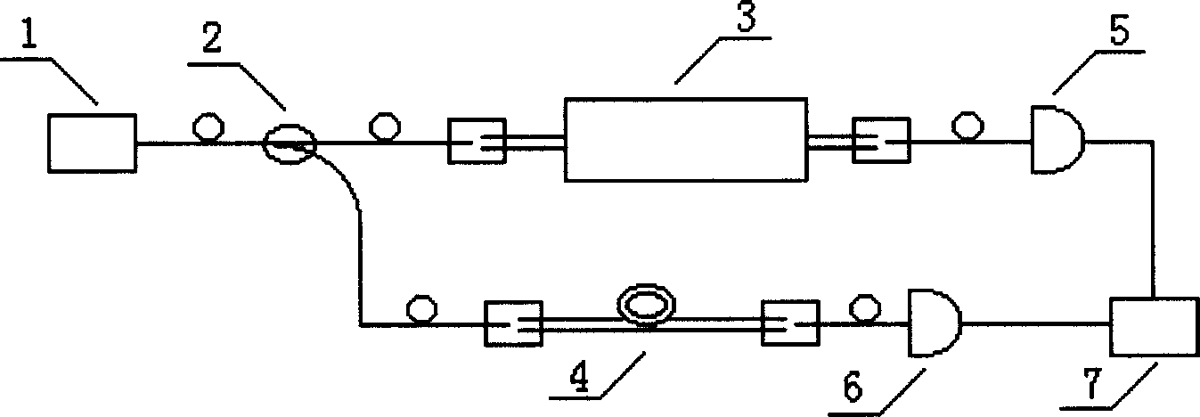
[0029] An embodiment of the present invention: as image 3 A fiber optic gas sensor shown includes a light source 1 connected by a common solid-core fiber, a coupler 2, a gas absorption cell 3, a comparison fiber 4, photodetectors 5, 6, and a signal acquisition and processing system 7. The optical fiber 8 in the gas absorption cell 3 and the comparison optical fiber 4 are Bragg hollow-core fibers, of course, photonic crystal hollow-core fibers can also be used. The connection relationship is as follows: light source 1 is connected to the input of coupler 2, one output of coupler 2 is connected to gas absorption cell 3, gas absorption cell 3 is connected to photodetector 5, and the other output of coupler 2 is connected to contrast fiber 4, and the contrast The optical fiber 4 is connected to the photodetector 6 again, and the outputs of the photodetectors 5 and 6 are connected to the signal acquisition and processing system 7 .

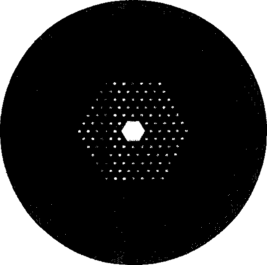
[0030] Wherein the structure of the gas absorp...


PUM


Abstract

The optical fiber gas sensor includes common solid fiber connected light source, coupler, gas absorbing pond, reference fiber and optoelectronic detectors, as well as signal acquiring and processing system, with the fiber in the gas absorbing pond and the reference fiber being micro structure hollow fibers. The present invention has amplification effect in loss measurement, and has the advantages of high sensitivity, simple structure, short response time, use safety and convenience, simultaneous measurement of several kinds of gas, etc.

Description

Technical field: [0001] The invention relates to the field of gas detection by optical means, and in particular belongs to a microstructure optical fiber gas sensor capable of measuring gas types and concentrations. Background technique: [0002] The detection of gas types and concentrations has important applications in production, life and scientific research, such as the detection of methane gas used for explosion protection in coal mines, the detection of automobile exhaust pollution, the detection of harmful gases in interior decoration, and the types of gases in laboratory research and concentration detection. Therefore, it is of practical significance to develop a fiber optic gas sensor with high sensitivity, simple structure, and safe and convenient use. [0003] The detection of gas type and concentration can be divided into: optical type, semiconductor type, solid electrolyte type, contact combustion type, electrochemical type, etc. according to the detection prin...

Claims


Application Information

Patent Timeline
IPC IPC(8): G01N21/01G01N21/31
Inventor 周国生贾清薛文瑞贾锁堂尹王宝马维光
Owner SHANXI UNIV
Learn More