Laser cutting device, laser cutting method and laser cutting system

A technology of laser cutting and conveying device, used in laser welding equipment, welding/welding/cutting items, transportation and packaging, etc., can solve the problems of unreliable support and delivery of parts, damage and establishment of parts on the reverse side, and improve production efficiency , the effect of preventing adhesion

Inactive Publication Date: 2005-08-10
TOYOTA STEEL CENT CO LTD
View PDF2 Cites 60 Cited by
  • Summary
  • Abstract
  • Description
  • Claims
  • Application Information

AI Technical Summary

Problems solved by technology

[0014] The laser cutting devices of the above-mentioned patent document 1 and patent document 2 use a sharp-top conveyor belt or a sharp-top workbench with a plurality of support members, so there are gaps between the sharp tops and the parts (especially small parts, etc.) that have been cut cannot be reliably cut. Borrow and Send Issues
In addition, when the cut parts supported by the pointed conveyor belt or the pointed table are adsorbed and held by the transport robot, etc., the cut parts should be pressed against the pointed conveyor belt or the pointed table, and the reverse side of the cut part may be damaged.
[0015] Therefore, the laser cutting system using the laser cutting devices of Patent Document 1 and Patent Document 2 cannot be established as an effective system, and cutting blank materials using existing blanking punches is the status quo.

Method used


Image

  • Laser cutting device, laser cutting method and laser cutting system
  • Laser cutting device, laser cutting method and laser cutting system
  • Laser cutting device, laser cutting method and laser cutting system

Examples


specific Embodiment

[0119] The present invention will be described in detail below through embodiments with reference to the accompanying drawings.

[0120] In the following embodiments, "left" and "right" represent the width direction Y of the sheet-like material (hereinafter simply referred to as the sheet) 11, and "front" and "rear" represent the feeding direction X of the sheet.

[0121] 1. Structure of laser cutting system

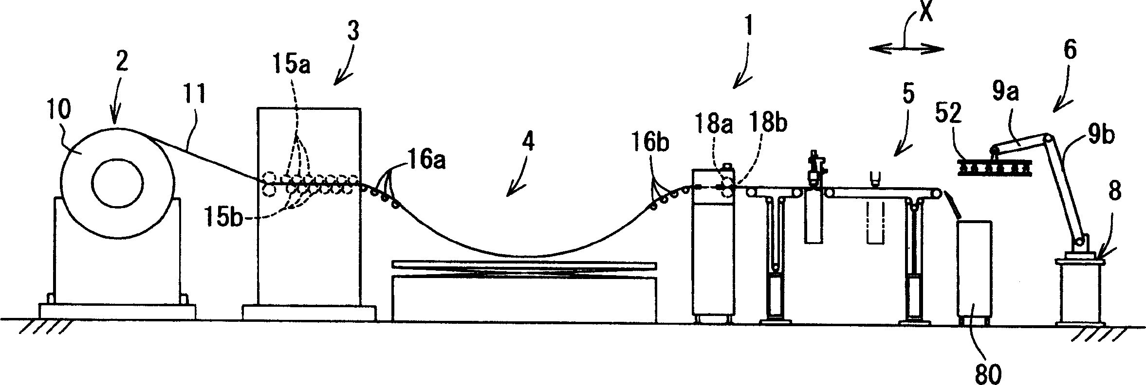
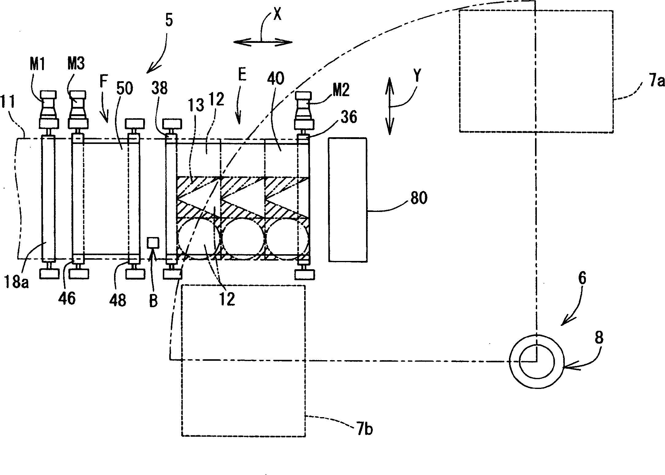
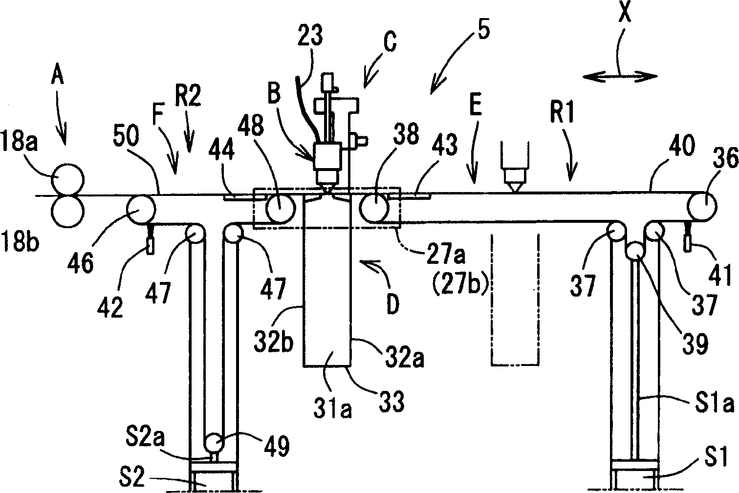
[0122] Such as figure 1 As shown, the structure of the laser cutting system 1 of this embodiment basically includes: a coil support device 2 disposed on the most upstream side, a leveling device 3 disposed on the downstream side of the coil support device 2, a leveling device disposed on the leveling device 3. The buffer curve forming part 4 on the downstream side, the laser cutting device 5 arranged on the downstream side of the buffer curve forming part 4, and the separation and recovery device 6 arranged on the downstream side of the laser cutting device 5.

[0123]...


PUM


Abstract

A laser cutting device, comprising a material feeding means for feeding a sheet-like material in a feeding direction, a processing head capable of radiating laser beam toward the material, a head moving means for moving the processing head in a material feeding direction X and a material lateral direction Y, an upstream side support means (belt conveyor mechanism F) for supporting the material on the upstream side of the lower part of the processing head and increasing / decreasing the support area (R2) of the material in the feeding direction according to the movement of the processing head in the feeding direction, and a downstream side support means (belt conveyor mechanism E) for supporting a part cut on the processing side lower part of the processing head and increasing / decreasing the support area (R1) of the cut part in the feeding direction according to the movement of the processing head in the feeding direction.

Description

technical field [0001] The invention relates to a laser cutting device, a laser cutting method and a laser cutting system. More specifically, the present invention relates to laser cutting of parts of various shapes through simple control, while preventing dust from adhering to and damaging the cut parts, and capable of reliably supporting and sending out the parts. Cutting device and laser cutting method. Moreover, the present invention relates to a very simple laser cutting system that does not require special molds and various coils with different widths, and can reduce the number of uncoils of coils as much as possible while reducing their inventory and space. [0002] The present invention is widely used in, for example, laser cutting of raw material as a material part of stamped parts such as automobiles and related fields. Background technique [0003] In recent years, the product update of automobiles has been carried out frequently, and the number of stamping part...

Claims


Application Information

Patent Timeline
Patent Type & Authority Applications(China)
IPC IPC(8): B23K26/08B23K26/10B23K26/16B23K26/38B23K26/60B23K26/70B23K101/16B23Q7/03B65G15/12
CPCB23K26/38B23K26/0846B23K26/0876B23K2201/16B23K26/16B23K2101/16
Inventor 清木辰彦浜地正则广濑康浩
Owner TOYOTA STEEL CENT CO LTD
Why Eureka
Try Eureka