Gas diffusion layer for fuel cell and its preparation method
A gas diffusion layer and fuel cell technology, which is applied in the parts of fuel cells, solid electrolyte fuel cells, electrical components, etc., can solve the problem that the current density cannot be further improved, and can reduce the Pt load, improve the performance, and reduce the reaction gas. Field uniform effect
- Summary
- Abstract
- Description
- Claims
- Application Information
AI Technical Summary
Problems solved by technology
Method used
Image
Examples
example 1
[0033] Example 1: Dilute polytetrafluoroethylene emulsion (Zhonghao Chenguang Chemical Research Institute, concentration is 60%) to 18%, then put carbon paper (Toray TGPH-060) into the prepared PTFE emulsion for 8min and take it out, Air-dried for 10 minutes, and then placed in a muffle furnace at 350°C for 20 minutes.
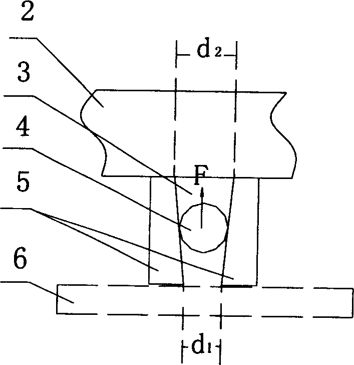
[0034] Take by weighing 2g of conductive carbon black (Vulcan XC-72, Cabot Co. particle size 30nm) and 50ml of distilled water and stir in a three-necked flask for 60min, and take by weighing 1.43g of polytetrafluoroethylene emulsion (Zhonghao Chenguang Chemical Research Institute, the concentration is 60%) and diluted to 10 ml with distilled water and added to the above stirred solution. After 30 minutes, 0.33g, 1.23g and 2.86g of ammonium chloride were added respectively, and the resulting mixtures were recorded as S-1, S-2 and S-3 respectively, and the detailed list is shown in Table 1. Continue to stir for 60 minutes, take out the ultrasonic vibration for...
example 2
[0038] Example 2: The hydrophobic treatment of carbon paper is the same as Example 1.
[0039] Weigh 2g of conductive carbon black (Vulcan XC-72, Cabot Co. particle size 30nm) and 50ml of distilled water and stir in a three-necked flask for 60min, weigh 1.43g of polytetrafluoroethylene emulsion (Zhonghao Chenguang Chemical Research Institute, concentration 60%) and diluted to 10 ml with distilled water and added to the above stirred solution. After 30 minutes, 0.33g, 1.23g and 2.86g of lithium carbonate were added respectively, and the formed mixed solutions were respectively recorded as P-1, P-2, and P-3. The detailed list of the mixed solutions is shown in Table 2. Continue to stir for 60 minutes, take out the ultrasonic vibration for 10 minutes and set aside.
[0040] Fix the hydrophobically treated carbon paper with an area of 100mm×200mm on the platform of a screen printing machine (PAD PRINTER ENG.CO.LTD, SPP-600FV). When printing, print the mixed solution P-3 first, ...
example 3
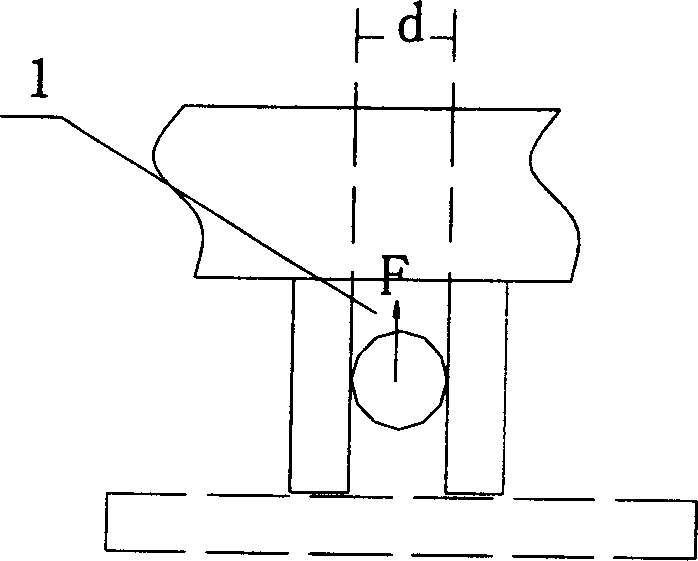
[0043] Example 3: The hydrophobic treatment of the carbon paper was the same as in Example 1 (obtaining the straight-through pore structure of the traditional microporous layer).
[0044] Take by weighing 2g of conductive carbon black (Vulcan XC-72, Cabot Co. particle size 30nm) and 50ml of distilled water and stir in a three-necked flask for 60min, and take by weighing 1.43g of polytetrafluoroethylene emulsion (Zhonghao Chenguang Chemical Research Institute, the concentration is 60%) and diluted to 10 ml with distilled water and added to the above stirred solution. After 30 minutes, add 1.23g of ammonium chloride, continue to stir for 60 minutes, take out the ultrasonic vibration for 10 minutes and set aside.
[0045] Fix the hydrophobically treated carbon paper with an area of 100mm×200mm on the platform of a screen printing machine (PAD PRINTER ENG.CO.LTD, SPP-600FV), pour out 20ml of the prepared solution, start the machine, and gently press the scraper repeatedly The s...
PUM
| Property | Measurement | Unit |
|---|---|---|
| particle size | aaaaa | aaaaa |
Abstract
Description
Claims
Application Information
 - R&D
- Intellectual Property
- Life Sciences
- Materials
- Tech Scout
- Unparalleled Data Quality
- Higher Quality Content
- 60% Fewer Hallucinations
Browse by: Latest US Patents, China's latest patents, Technical Efficacy Thesaurus, Application Domain, Technology Topic, Popular Technical Reports.
© 2025 PatSnap. All rights reserved.Legal|Privacy policy|Modern Slavery Act Transparency Statement|Sitemap|About US| Contact US: help@patsnap.com


