

Electronic heat pump device, electronic equipment using electronic heat pump device and method of manufacturing electronic heat pump device
一种电子热泵、冷藏装置的技术,应用在使用电/磁效应的机器、不带控制装置的管、动能转变为电能的发电机等方向,能够解决电力消耗增大、热转移损失、增加无关系电路电力消耗等问题,达到防止热的倒流、减少部件数的效果
- Summary
- Abstract
- Description
- Claims
- Application Information
AI Technical Summary
Problems solved by technology
Method used
Image

Examples
no. 1 Embodiment
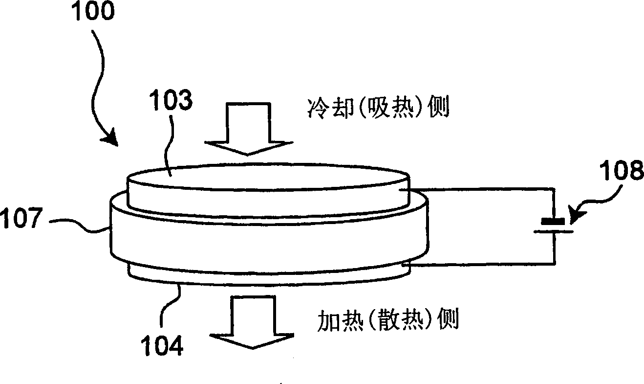
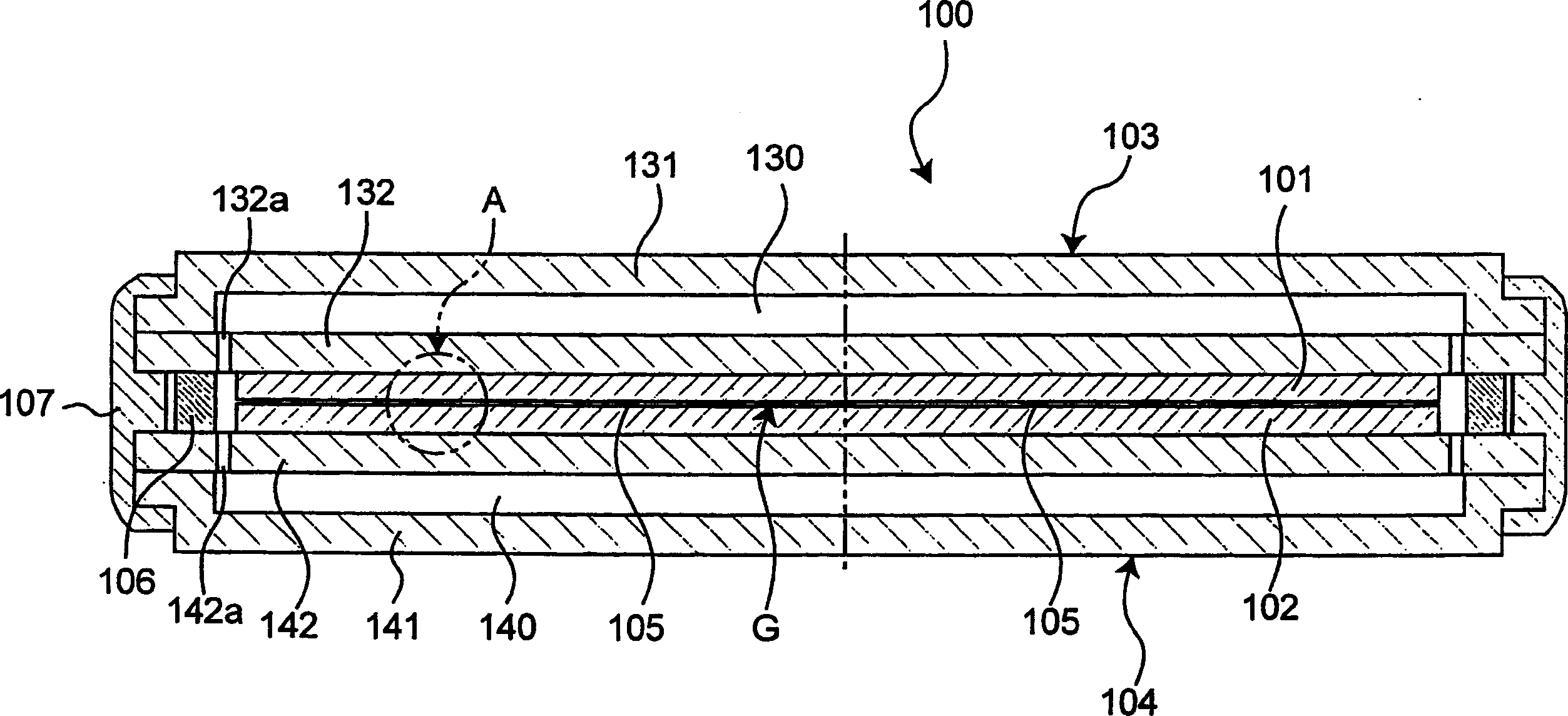
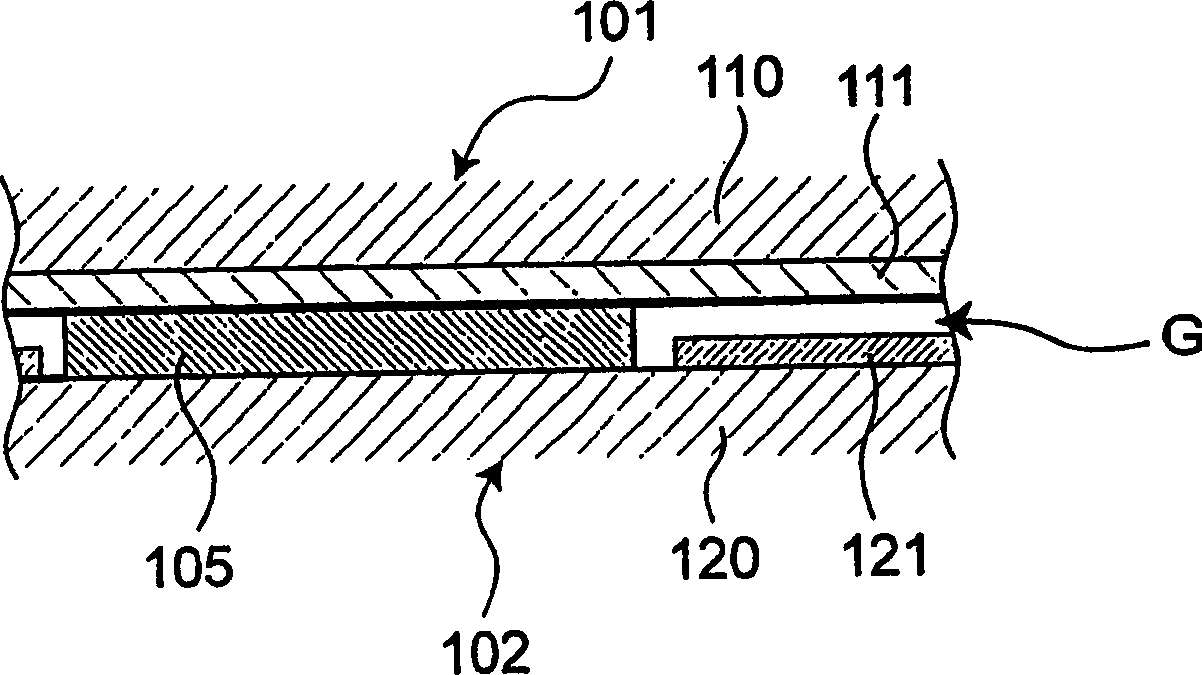
[0249] figure 1 A perspective view showing an embodiment of the electronic heat pump device of the present invention. figure 2 shows a longitudinal sectional view of the electronic heat pump device, image 3 express figure 2 Enlarged view of part A.
[0250] The electronic heat pump device 100 includes: a first supporting member 103 with electrical and thermal conductivity; The first internal electrode 111 on the other side has a second support member 104 with electrical and thermal conductivity, and a second semiconductor substrate 120 connected to the second support member 104 capable of conducting electricity and heat on one side, and is arranged on the second semiconductor substrate. The second internal electrode 121 on the other side of 120 is arranged between the first support member 103 and the second support member 104 at the same time, and the distance between the first support member 103 and the second support member 104 is kept constant. An electrically and th...
no. 2 Embodiment
[0320] Figure 14 Another embodiment of the present invention is shown, and a plurality of modules using the electronic heat pump device 100 of the first embodiment described above are shown. That is, the module has, for example, a SiO 2 A box-type insulating heat insulating material 146 as a main component and a plurality of above-mentioned electronic heat pump devices 100 embedded in the insulating heat insulating material 146 . Although the plurality of electronic heat pump devices 100 are connected in series, they may be connected in parallel or mixed in series and parallel. In addition, it is easy to understand that the number of electronic heat pump devices 100 used in the module is determined by the application and is not limited to what is shown in the figure.
[0321] If a module with the above-mentioned structure is used, it may be possible to realize a wide-area cooling plate through modularization with a cooling capacity that cannot be handled by a single device....
no. 3 Embodiment
[0323] Secondly, as another embodiment of the present invention, there are figure 2 Structural improvement. In this example, figure 2The hollow portion 130 of the above-mentioned first support member (emitter-side stem) 103 and the hollow portion 140 of the above-mentioned second support member (collector-side stem) 104 are filled with the above-mentioned two stems 103 and 104 respectively. Thermally conductive materials below the coefficient of thermal expansion (not shown). With such a thermally conductive material, heat generated at the emitter electrode 101 and the collector electrode 102 can be efficiently transferred to an external heat transfer portion.
[0324] In addition, the thermally conductive material is a thin wire or plate-shaped material having at least one deformable property among Ti, Al, Zr, Fe, V, without reducing the heat conduction effect, and the above-mentioned thermally conductive material absorbs vacuum Gas is generated inside during sealing and...
PUM
 Abstract
Description
Claims
Application Information