
Separator and fuel cell using that separator

A fuel cell and separator technology, which is applied in the direction of fuel cells, fuel cell additives, fuel cell grouping, etc., can solve the problems of narrow gas supply path, blockage of flow path, hindering the diffusion of supplied gas, etc., and achieve sufficient gas diffusion and suppression The effect of an increase in collector resistance

Inactive Publication Date: 2005-11-02
EQUOS RES
View PDF2 Cites 1 Cited by
  • Summary
  • Abstract
  • Description
  • Claims
  • Application Information

AI Technical Summary

Problems solved by technology

Because in these past technologies, the flow channel plate or the conductive pad is connected to the electrode through the current collector or the current plate, the gas supply path is narrowed due to the offset of the hole position in these overlapping parts, and when the adhesion reaction occurs in the narrow part Droplets of water or supply water may clog the flow path and prevent the supply gas from diffusing to the electrodes.

Method used


Image

  • Separator and fuel cell using that separator
  • Separator and fuel cell using that separator
  • Separator and fuel cell using that separator

Examples


no. 1 Embodiment

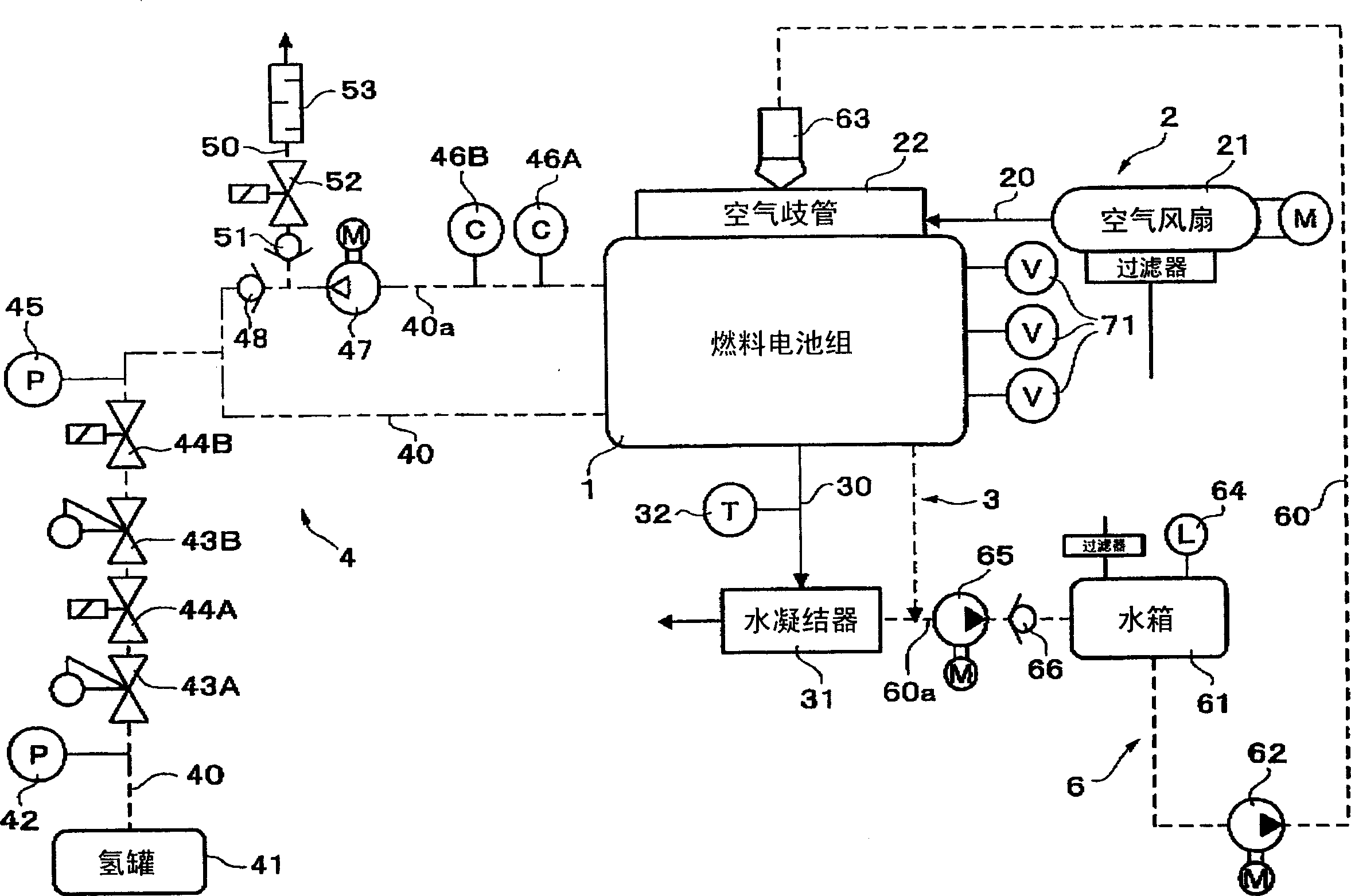
[0033] Embodiments of the present invention will be described below with reference to the accompanying drawings. figure 1 This is the structure of a fuel cell system for a vehicle using the fuel cell stack 1 of the present invention. The fuel cell system includes an air supply system (indicated by a solid line in the figure) 2 including an air fan 21 as an air supply mechanism with a fuel cell stack 1 as a main body, and an air supply system including a water condenser 31 as an air supply mechanism. A fuel cell main body consisting of a discharge system 3; a fuel supply system (indicated by a dashed line in the figure) 4 including a hydrogen tank 41 as a hydrogen supply mechanism; a water supply system (indicated by a dotted line in the figure) for moistening and cooling the reaction part )6.

[0034] An air fan 21 disposed in the main body of the fuel cell is connected to an air manifold 22 through an air supply passage 20, and the air manifold 22 is connected to a case (not...


PUM

PropertyMeasurementUnit
thicknessaaaaaaaaaa

Abstract

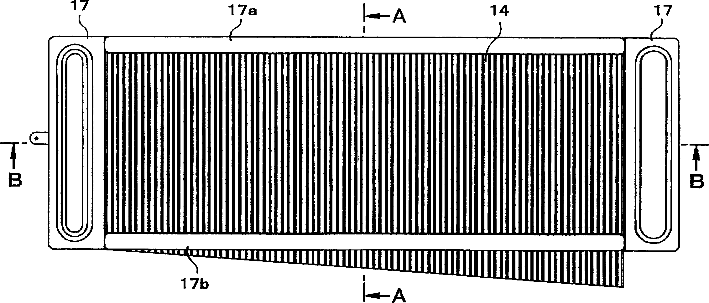
A separator includes an imperforate separator substrate and spacer plates that are interposed between electrodes and the separator substrate. The spacer plates are formed of mesh and have rectangular wave-shaped cross-sections. Top portions of the rectangular waves that abut against the electrodes serve as gas diffusion portions. Adjacent side portions and portions between waves together are rectangular and serve as spacer portions which define gas passages between the gas diffusion portions and the separator substrate. Air holes that provide intercommunication between adjacent gas passages are provided in the spacer portions. As a result, gas can be supplied downstream of a gas passage that has become narrow or blocked due to a water droplet remaining in the passage.

Description

technical field [0001] The present invention relates to a fuel cell, in particular to a separator interposed between its cells. Background technique [0002] There are various types of fuel cells. Among them, the polymer electrolyte fuel cell has a low reaction temperature and a small volume, which is suitable for being mounted on a vehicle. This type of fuel cell utilizes, as a unit, a membrane-electrode assembly (MEA) formed by sandwiching a polymer electrolyte membrane between a gas diffusion electrode (consisting of a catalyst layer and a porous support layer (gas diffusion layer)), and the outer side of which is arranged with a simultaneous The separators also serve as supply passages for reaction gases such as hydrogen (fuel gas) or oxygen (oxidant gas), and form a laminated structure. The separator can prevent the reaction gas from permeating to the adjacent MEAs in the stacking direction, and at the same time, draws the generated electric current to the outside and ...

Claims


Application Information

Patent Timeline
Patent Type & Authority Applications(China)
IPC IPC(8): H01M2/00H01M2/14H01M8/02H01M8/04H01M8/10H01M8/24
CPCH01M8/04291H01M2008/1095H01M8/0245H01M8/0232H01M8/2405H01M8/04164H01M8/0254Y02E60/50H01M8/2483H01M8/242H01M8/0267H01M8/2457H01M8/2484H01M8/0258F21L14/00F21V15/02F21V29/15F21V21/08F21S6/003F21W2131/402H01M8/026
Inventor 堀口宗久
Owner EQUOS RES
Learn More