
Underground intelligent vehicle detector

A technology of intelligent vehicles and detectors, applied in the field of detection devices, can solve the problems of incomplete detection information, single detection method, inconvenient installation, etc., and achieve the effects of low installation environmental conditions, increased information volume, and improved reliability

Inactive Publication Date: 2005-12-14
林贵生
View PDF1 Cites 16 Cited by
  • Summary
  • Abstract
  • Description
  • Claims
  • Application Information

AI Technical Summary

Problems solved by technology

[0003] At present, the detectors of relevant vehicles mostly use passive infrared rays to detect vehicle signals and transmit them to the traffic command department after amplifying them, such as the "vehicle detection device" with the application number 98802297.4 of the patent Siemens Corporation; The coil is a detection device. When the vehicle passes by the large induction coil, the vehicle passes by or stops on the large induction coil, so that the inductance of the coil changes, so that the electrical signal output by the detection circuit composed of the coil and other circuits also changes accordingly. The detection signal of the vehicle is changed to form a vehicle detection signal, generally a frequency signal, which is sent to a processor for processing to obtain traffic information such as traffic flow. These detection devices have a single detection method for vehicles, incomplete detection information, large volume, inconvenient installation, and When the road surface is seriously damaged, it is easy to be damaged due to cracks in the road surface, etc.
In addition, the United States produces a permanent wireless vehicle recorder that uses vehicle magnetic imaging (VMI) technology to measure traffic flow. When the vehicle is detected at the location or parked near its installation location, it has limitations and deficiencies in function or performance, and cannot fully meet the monitoring, management, and command systems of urban traffic intersections, parking lots, and road network traffic conditions. Requirements for Vehicle Detection Devices

Method used


Image

  • Underground intelligent vehicle detector
  • Underground intelligent vehicle detector
  • Underground intelligent vehicle detector

Examples


Embodiment 1

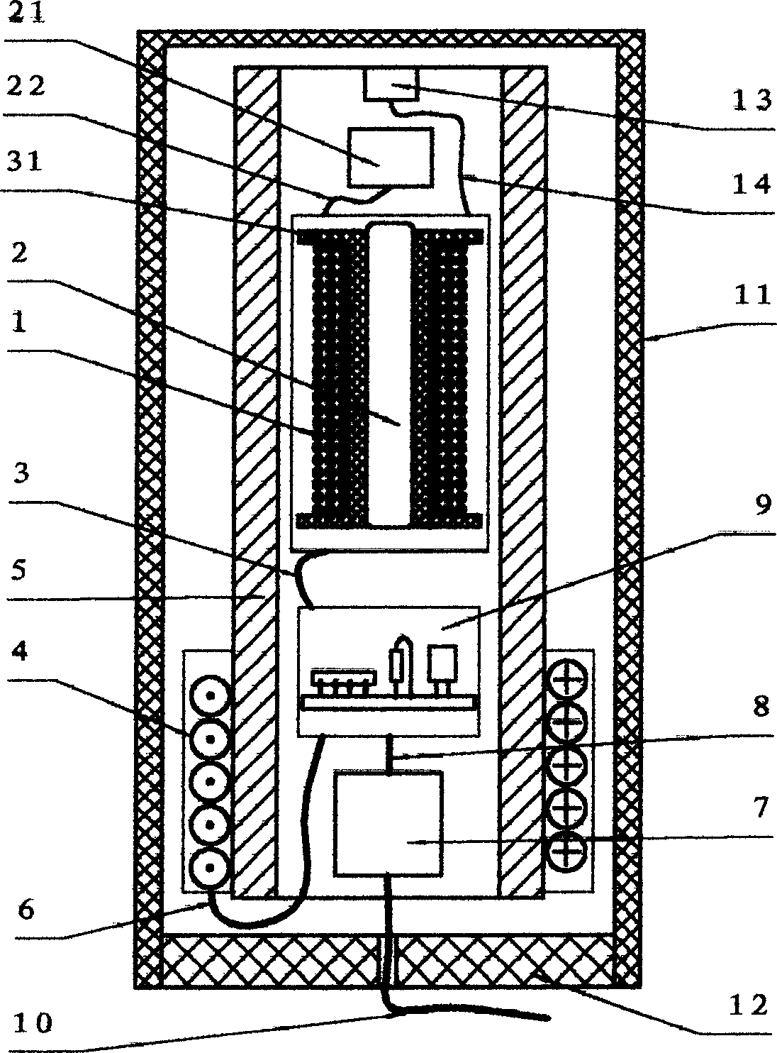
[0026] Such as figure 1 As shown, the detector of this embodiment is composed of a temperature sensor (13), a temperature sensor lead wire (14), a monolithic magnetic field sensor integration (21), a magnetic field sensor lead wire (22), a vehicle geomagnetic induction coil (1), and ground Magnetic induction coil skeleton (31), geomagnetic induction coil core (2), geomagnetic induction coil lead wire (3), metal induction detection coil (4), metal induction detection coil core (5), circuit module circuit board (9) , A connecting cable (8), a long-distance input / output serial interface circuit (7), a power cord and a signal cable (10), a plastic shell body (11) and a plastic shell cover (12). The metal induction detection coil (4) is wound on the lower section of the high-permeability "round tube" metal induction detection coil core (5), and a temperature sensor (13) is set up in the cavity in the center of the core (5) , Monolithic integrated magnetic field sensor (21), vehicle ge...

Embodiment 2

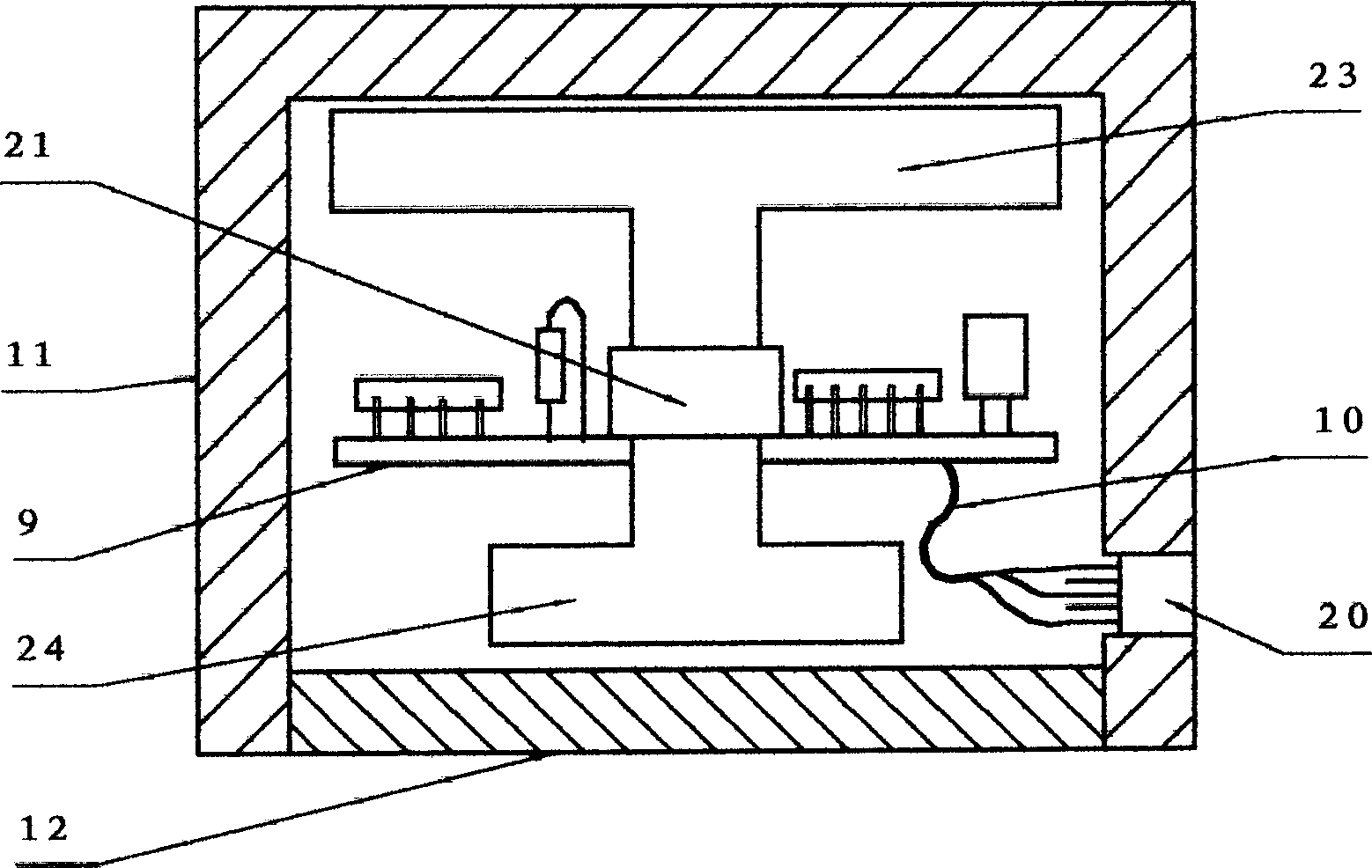
[0030] Such as image 3 As shown, the detector of this embodiment consists of a housing body (11) and a housing bottom cover (12), a Hall linear magnetic field sensor (21), a geomagnetic concentrator (23, 24), a circuit module (9), and a transmission A connecting cable (10) and an interface socket (20) are formed. It can detect vehicle signal data when a vehicle passes, approaches, stops or leaves the detection device.

[0031] Such as Figure 4 As shown, the circuit schematic diagram of this embodiment, the power supply is supplied by the I / O interface; the vehicle geomagnetic quantity detection device is composed of AC Hall linear magnetic field sensor and U1, AC is SL3501M / TU2, U1 is AMP04; U2 is belt string The 16-bit A / D converter CS5509 with line interface constitutes a signal processing / logic processing unit; I / O is a 9-pin serial interface socket / plug, which constitutes the detector transmission interface unit.

[0032] According to the working principle of the above-menti...

Embodiment 3

[0034] Such as Figure 5 , 6 As shown, the detector of this embodiment consists of a vehicle geomagnetic induction coil (1), a geomagnetic induction coil skeleton (31), a geomagnetic induction coil core (2), a geomagnetic induction coil lead wire (3), a fixing nut (32), A circuit module circuit board (9), a power cord and a signal cable (10), a shell body (11) and a shell cover (12) are composed.

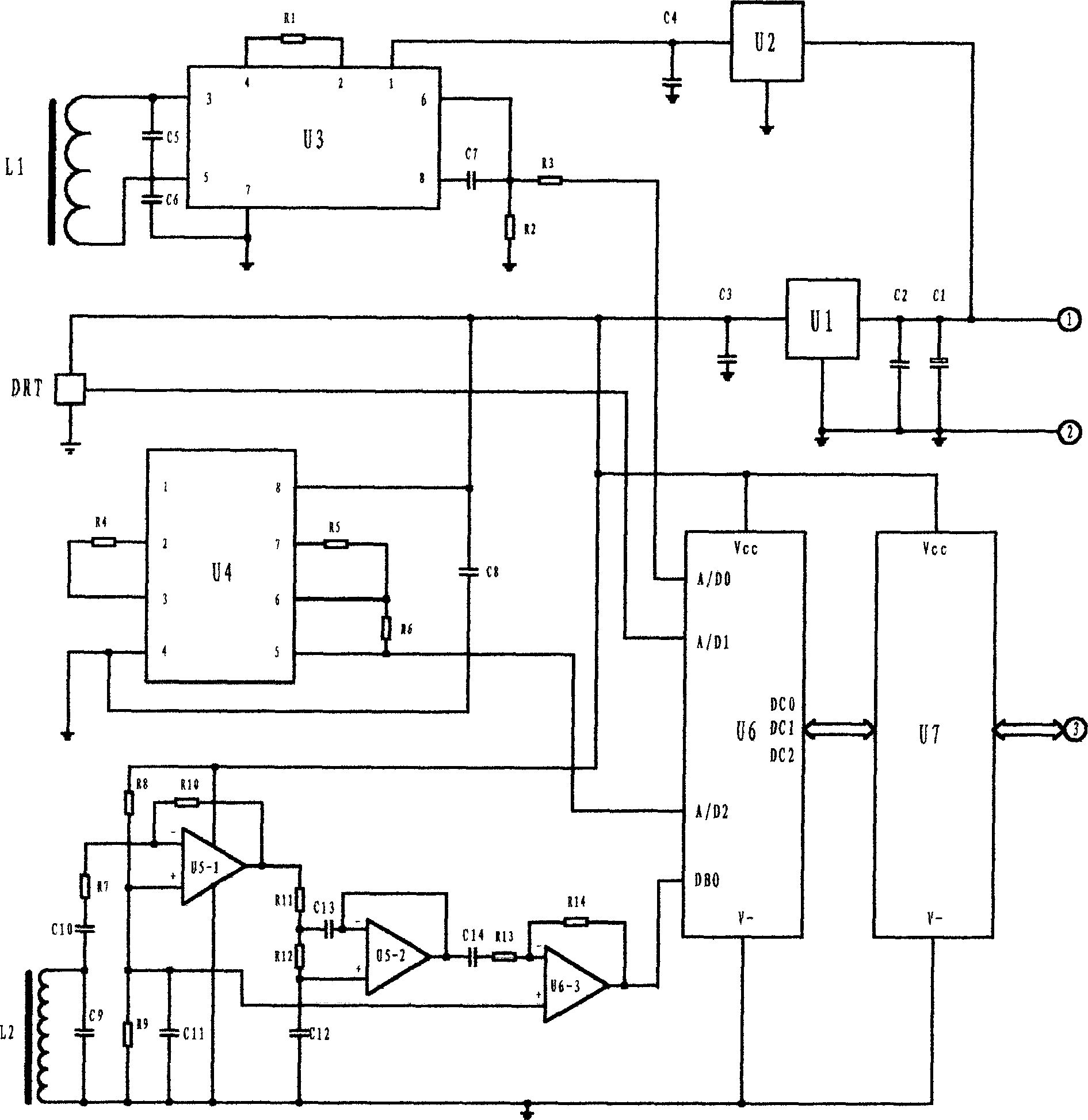
[0035] Such as Figure 7 As shown, the circuit principle diagram of this embodiment, the power supply is composed of U1, C1, C2, ① and ②, U1 is a 78L105 three-terminal voltage regulator; the vehicle geomagnetic induction detection device is generated by the geomagnetic induction coil L and the coil induced voltage signal The detection / processing circuit is composed of C3, C4, R1-R6, U2-1 and U2-2. U2 is a two-op-amp LM258 / 358; U3 is an AVR microcontroller, and U3 is a The main components constitute an intelligent signal processing / logic processing unit for signal acquisition, data analys...


PUM


Abstract

The intelligent geographic vehicle detector consists of detecting unit, signal processing and logical processing unit for processing signal from the detecting unit through amplification, filtering, shaping, comparison, sensitivity regulation, environment compensation, A / D acquisition, automatic calibration, logic analysis, coding, storing, etc., signal conversion / transmission interface unit, power source and casing. It may have sub-detector connected. It may be used in detecting vehicle to obtain various dynamic and static information, including path, speed, parking time, running direction, etc. and is suitable for traffic management, vehicle monitoring, toll gate management, park management, etc.

Description

Technical field [0001] The invention relates to a detection device, in particular to a buried intelligent vehicle detector. The device can be used in a city or highway traffic command and management system and a vehicle static management system, and can be used for vehicle driving, side running, traffic flow, etc. Detection of vehicle dynamic or static information such as road occupation, traffic jam, parking time, etc., suitable for traffic light green wave belt control system, electronic police camera system, vehicle toll station system, vehicle access control system, parking lot management system and road network traffic monitoring and management System etc. Background technique [0002] With the development of economy and the improvement of people's living standards, cars are getting closer and closer to people's lives. Urban traffic and highway traffic jams occur from time to time, especially the traffic conditions of large and medium-sized cities have been of concern to the...

Claims


Application Information

Patent Timeline
IPC IPC(8): G01S7/285
Inventor 林贵生
Owner 林贵生
Learn More