

Excited quasi-molecular lampbulb
A technology of excimer lamps and excimers, applied in discharge lamps, electrical components, circuits, etc., can solve the problems of internal electrode size restrictions, inability to arrange, difficult discharge areas, etc., to achieve greater design flexibility and reduce size , long life effect
- Summary
- Abstract
- Description
- Claims
- Application Information
AI Technical Summary
Problems solved by technology
Method used
Image

Examples
no. 1 example
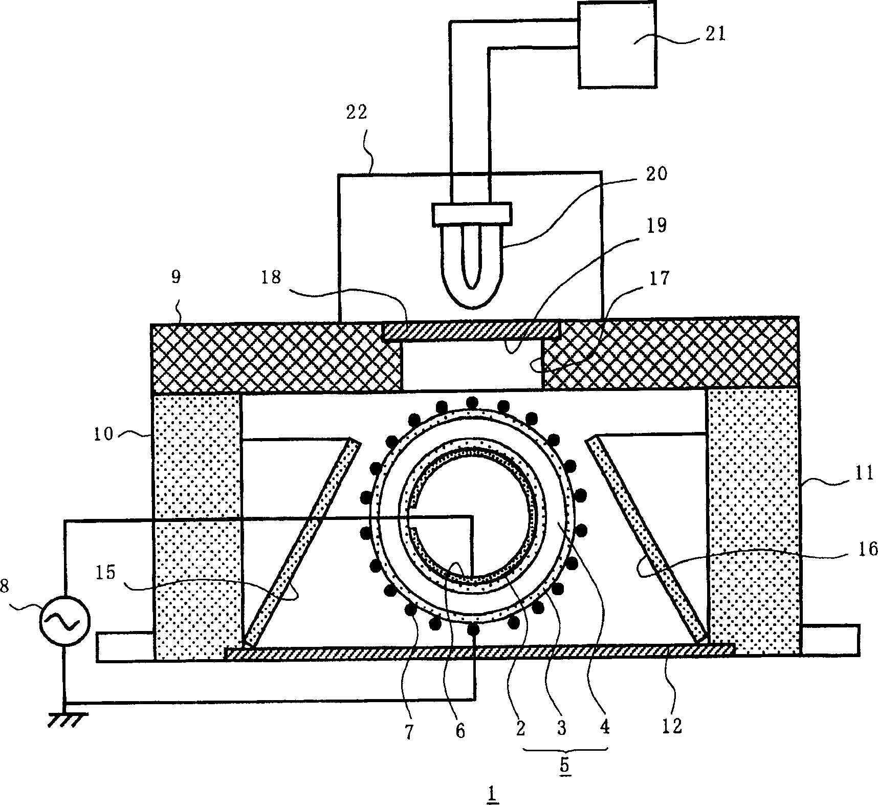
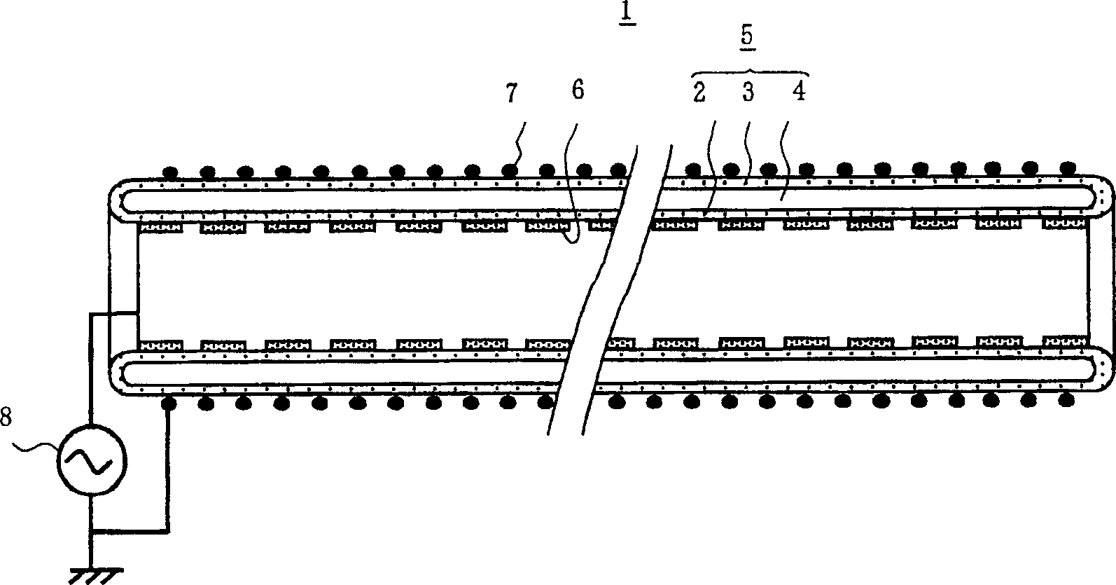
[0052] figure 1 A sectional view showing an excimer lamp device according to a first embodiment of the present invention. figure 2 A longitudinal sectional view of the excimer lamp 1 used in this excimer lamp device is shown.
[0053] The excimer lamp 1 has a vessel 5 made of quartz glass and having a length of 850 nm. Inside the container 5 are provided an inner tube 2 whose outer diameter is 23 mm and whose thickness is 1.2 mm, an outer tube 3 whose outer diameter is 35 mm and whose thickness is 1.2 mm, and an inner tube 2 and an outer tube 3 formed by a concentric arrangement. Airtight double cylindrical discharge space 4 in the space.
[0054] Xenon used as a discharge gas was enclosed in the discharge space 4, and its pressure was set to 500 Torr. A strip-shaped stainless steel inner electrode 6 is arranged in a circular shape along its surface on the surface of the inner tube 2 outside the discharge space inside the discharge vessel 5 . A grid-shaped external electr...
no. 2 example
[0072] Figure 4 A sectional view showing an excimer lamp in an excimer lamp device according to a second embodiment of the present invention.
[0073] Compared with the first embodiment, the significant difference in the excimer lamp device according to the second embodiment lies in the following two points: First, the stable starting voltage of the excimer lamp is changed so as to have a frequency of 2 MHz and 8.1 kVp- p; and secondly, using a halogen lamp and a power circuit for starting the halogen lamp as an ultraviolet emitter. Other configurations are substantially the same as those of the first embodiment, so the same reference numerals used in the first embodiment are used to describe these elements.
[0074] The halogen lamp 23 (power consumption 100W, rated voltage 12V) used as an ultraviolet emitter mainly reflects light whose wavelength region is in the visible and infrared range, but a small part of the light falls within the wavelength range of 250nm to 380nm i...
no. 3 example
[0085] Figure 5 A vertical longitudinal sectional view showing the excimer lamp of the excimer lamp device according to the third embodiment of the present invention taken along the longitudinal axis. exist Figure 5 in, showing the formation of figure 1 or 4 front wall 13 and rear wall 14 not shown.
[0086] Compared with the second embodiment, the excimer lamp device according to the third embodiment is mainly different in the following: an infrared transmission filter 30 for transmitting infrared rays in the light emitted from the excimer lamp 1 is provided; An infrared detector is a silicon photodiode 40 for detecting infrared rays, and a lighting controller 50 for controlling the excimer lamp 1 and the halogen lamp 23 to be switched on. The other configurations are substantially the same as those of the first and second embodiments, so the same reference numerals in the first and second embodiments are used to describe these elements.
[0087] Image 6 A block diagr...
PUM
 Abstract
Description
Claims
Application Information